Distributed image display method

An image display and distributed technology, applied in image communication, television, electrical components, etc., can solve the problems of large network load, high CPU load, and the time of receiving data is far from the time of receiving data, etc., to ensure synchronization , Improve synchronization and reduce load

Inactive Publication Date: 2012-07-11
GUANGDONG VTRON TECH CO LTD
View PDF0 Cites 0 Cited by
  • Summary
  • Abstract
  • Description
  • Claims
  • Application Information

AI Technical Summary

Problems solved by technology

The disadvantage of this solution is that: because the entire image data is transmitted, the network bandwidth requirement is relatively high; when there are many clients, the image server has to send all data to each client, resulting in a large network load; At the same time, due to the large amount of data transmission in distributed display, when the image server transmits massive data to the client in turn, the time when the first client receives data is far from the time when the last client receives data. As the number of clients increases, this problem will become more and more serious, resulting in low synchronization of the technical solution
The disadvantage of this solution is: because the area requested by each client is generally inconsistent, and the compressed data cannot be disassembled and reused, therefore, for different client connections, the same data may have to be processed With multiple compressions, the CPU load of the image server is high; at the same time, because the request time of each client is inconsistent with the request area, every time the image server responds to a request, it must compress the request area once, which will also cause data reception between clients Out of synchronization, thus resulting in poor overall synchronization of the technical solution

Method used


Image

  • Distributed image display method
  • Distributed image display method
  • Distributed image display method

Examples


Embodiment Construction

[0027] The present invention will be described in further detail below in conjunction with the embodiments and the accompanying drawings, but the embodiments of the present invention are not limited thereto.

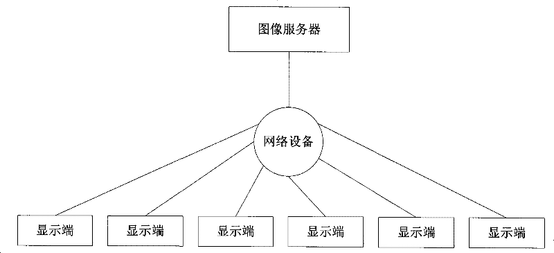
[0028] Such as figure 1 As shown, in the distributed image display system, the image server is respectively connected to multiple display terminals through network devices (such as hubs, routers, switches, etc.).

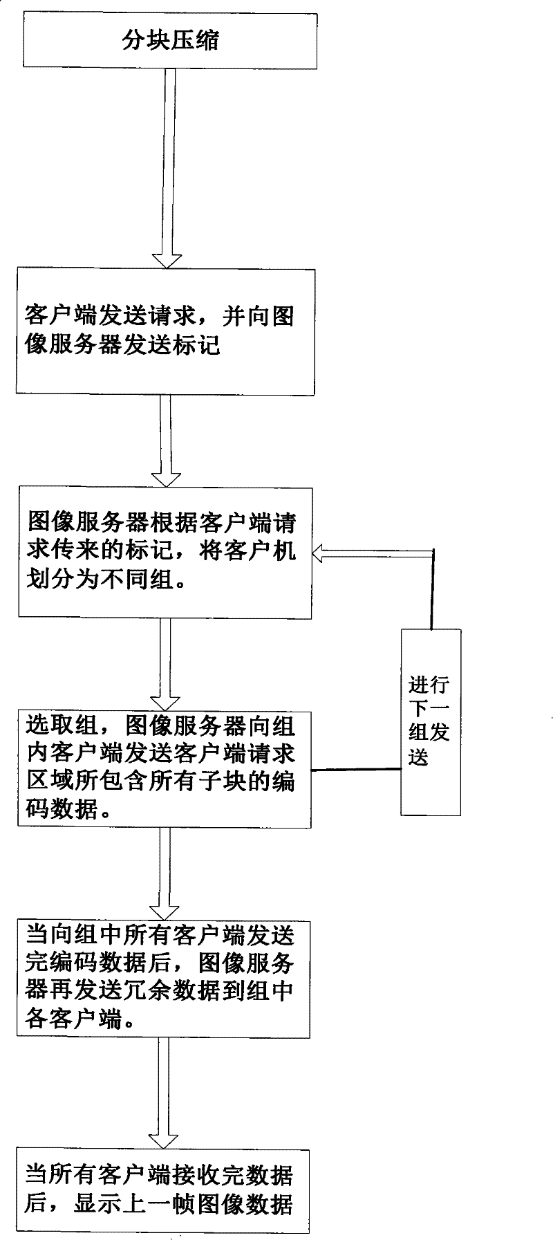
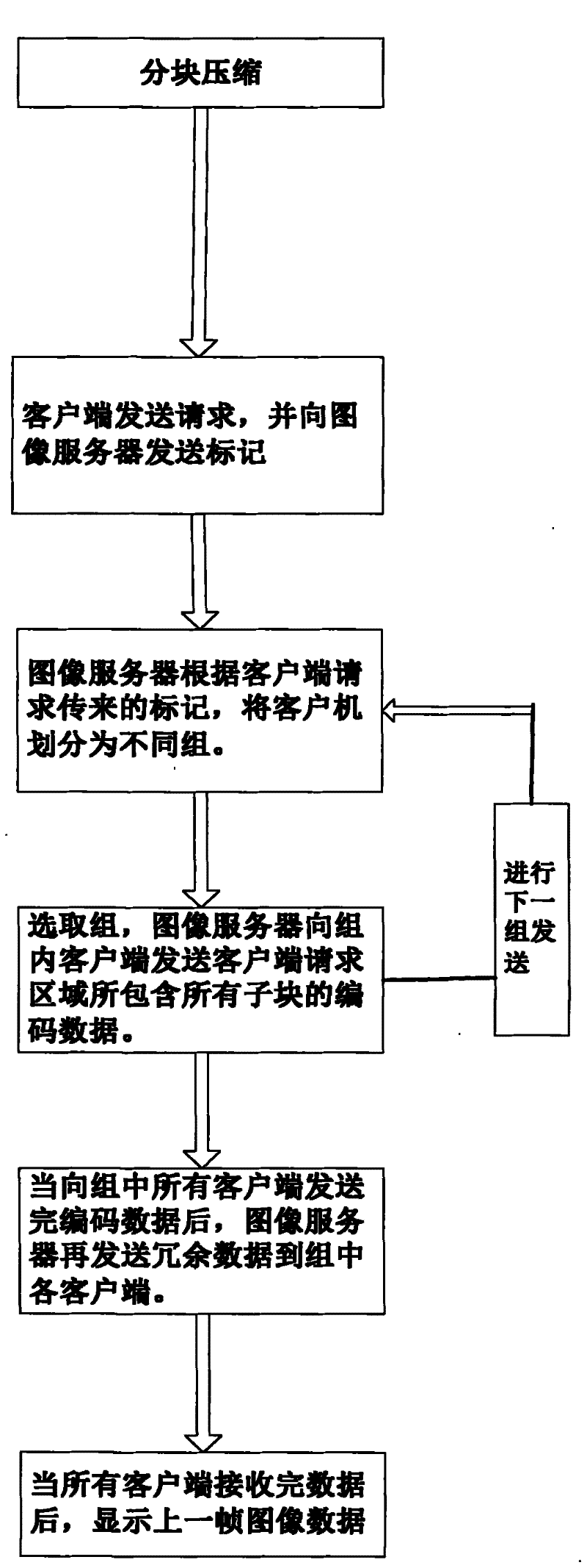
[0029] As shown in the figure, the workflow of the distributed image display system includes the following steps:

[0030] (1) According to the size of the self-defined image sub-block, the image server divides the whole image into several image sub-blocks, and then encodes each image sub-block; the size of the self-defined image sub-block is 8×8, 16 ×16, 32×32 or 64×64, preferably 8×8; because the smaller the block, the less data redundancy when dividing the entire image into blocks, but it will have a negative effect if it is too small, because each small b...


PUM


Abstract

The invention provides a distribution image display method which includes the steps that (1) an image server divides the whole image into a plurality of image sub-blocks equally according to the size of the user-defined image sub-block; and then each image sub-block is encoded; (2) the client sends a request; the image server sends the encoded data of all the image sub-blocks contained in the request region to the corresponding client according to the request region of the client; when the encoded data is sent, the image server sends the redundancy data to the client; (3) the client receives data from the server, including the encoded data and the redundancy data and displays the image data of the former frame. The distribution image display method can reduce the CPU load and the network load of the image server and guarantee the synchronism of the distribution image display.

Description

technical field [0001] The invention relates to a distributed image display technology, in particular to a distributed image display method. Background technique [0002] In the prior art, there are the following two solutions for distributed image display: [0003] The first method is to encode and send the entire image. The image server encodes the entire image once to obtain the encoded data of the entire image, and then sends the same data to all clients, and the clients crop and display it separately. The disadvantage of this solution is that: because the entire image data is transmitted, the network bandwidth requirement is relatively high; when there are many clients, the image server has to send all data to each client, resulting in a large network load; At the same time, due to the large amount of data transmission in distributed display, when the image server transmits massive data to the client in turn, the time when the first client receives data is far from the...

Claims


Application Information

Patent Timeline
Patent Type & Authority Patents(China)
IPC IPC(8): H04L29/06H04N7/26H04N19/112H04N19/127H04N19/176
Inventor 冯海勇谷新征蔡才冠刘亚平
Owner GUANGDONG VTRON TECH CO LTD
Why Eureka
Try Eureka