Crimping die for shell crimping

A technology of tight mouth and shells, which is applied in the direction of ammunition, weapon accessories, offensive equipment, etc., can solve the problems of high energy loss, low mechanical efficiency, and large force on the mechanism, so as to avoid huge friction, prolong the life of the equipment, and improve the mechanical efficiency Effect

Active Publication Date: 2012-05-30
廊坊智通机器人系统有限公司
View PDF0 Cites 0 Cited by
  • Summary
  • Abstract
  • Description
  • Claims
  • Application Information

AI Technical Summary

Problems solved by technology

Although the existing tight-mouth dies have passed the test of perennial production, there are still some inherent defects: 1. The current tight-mouth dies adopt the conical force-assisted method to cause the depth of the tight-mouth line of each currently-used tight-mouth die. Inconsistency affects the consistency of the elastic force after tightening the mouth
2. The working process of the tight die cannot be controlled, and the tight die cannot be opened when there is a slight imbalance in the movement of the equipment.
3. The mechanical efficiency of the current tight die is low, the mechanism is stressed, and the energy loss is high

Method used


Image

  • Crimping die for shell crimping
  • Crimping die for shell crimping
  • Crimping die for shell crimping

Examples


Embodiment Construction

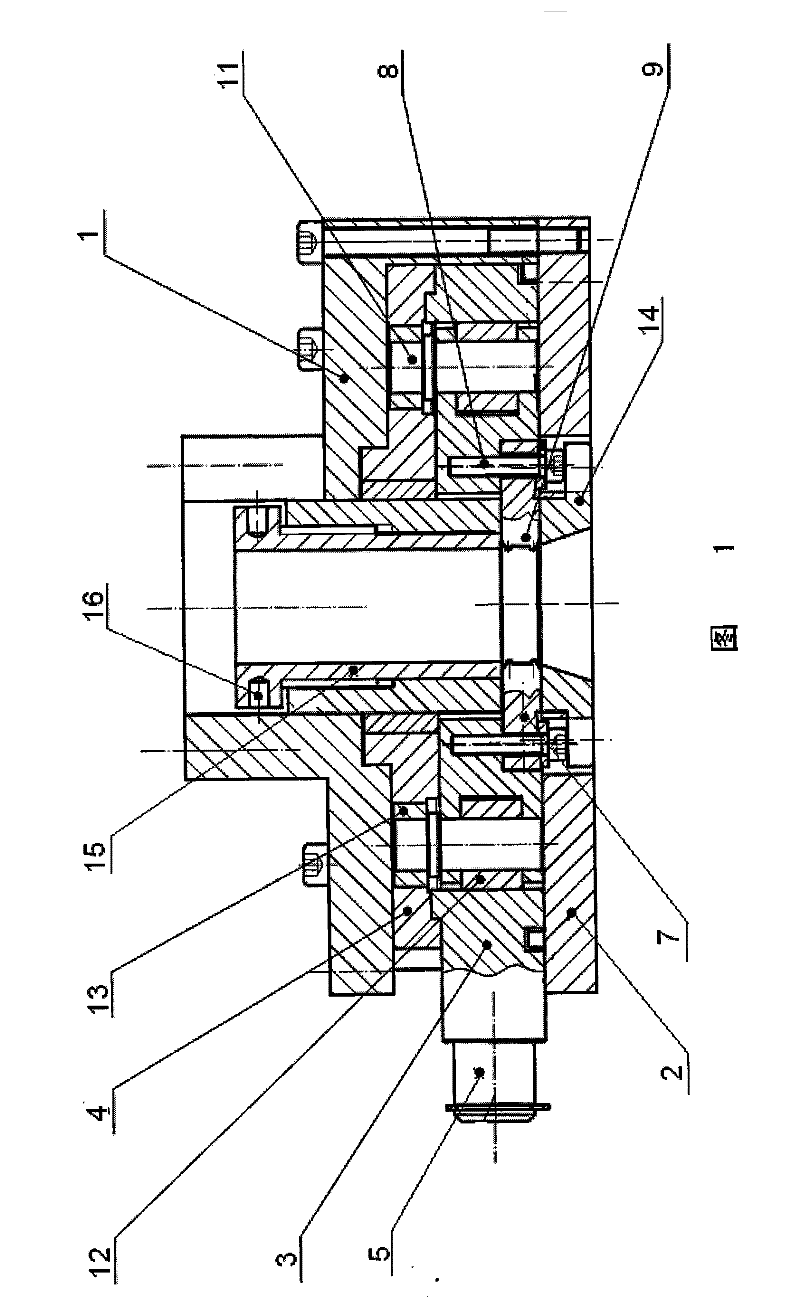
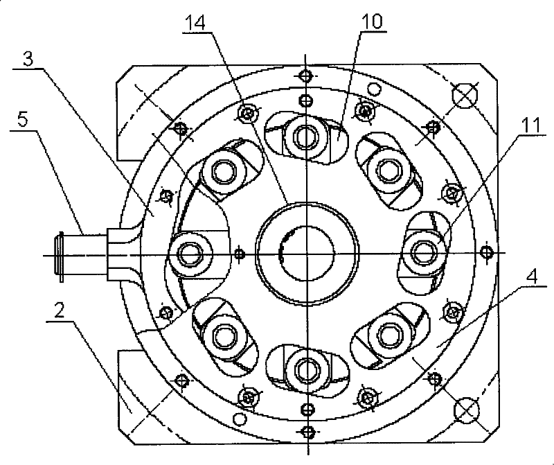
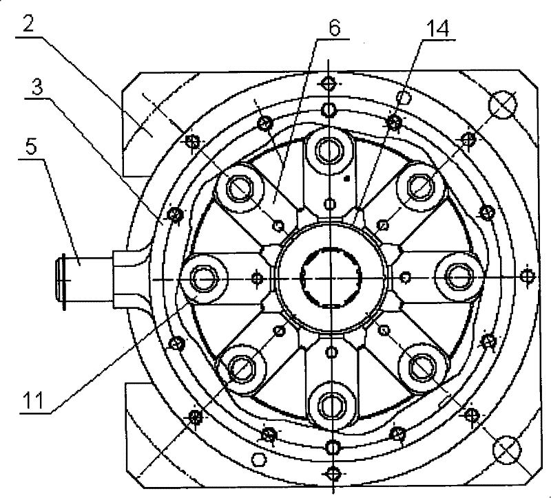
[0011] The present invention will be described in detail below in conjunction with the accompanying drawings and embodiments.

[0012] Such as figure 1 , figure 2 , image 3 As shown, the present invention comprises a housing 1, a base 2, a lower dial 3 and an upper dial 4 respectively having a central hole, and a toggle handle 5 is arranged on the outer ring of the lower dial 3, and radially Evenly have 8 (only take this as an example, not limited to this) long holes 6, lower dial 3 inner ring circumferential direction evenly have 8 (only take this as an example, not limited to this) chute, each A tight mouth slide block 7 is all installed in each chute, and is connected together with lower dial 3 by screw 8, and the front end of tight mouth slide block 7 replaceable tight mouth mold valve 9 is installed. The 4 circles of the upper dial are also evenly provided with 8 (only as an example, not limited to this) long holes 10 along the circumferential direction. Lower dial ...


PUM


Abstract

The invention relates to a fastening mould used for fastening a shell, which is characterized in that: the fastening mould comprises a shell which is provided with a separate center hole, a base, a lower drive plate and an upper drive plate; circumference of the lower drive plate are provided with a group of slot holes uniformly along radical direction, the center hole of the lower drive plate isprovided with a group of chutes uniformly along circumferential direction, each chute is provided with a fastening block, the front end of the fastening block is provided with a fastening valve model; the upper drive plate are also provided with a group of slot holes uniformly along circumferential direction; the lower drive plate and the upper drive plate are connected with each other through the pin rolls which are arranged in the drive plates, the pin roll is provided with a roller and a roller return; the shell, the base, the lower drive plate and the upper drive plate are connected through a pivot, the pivot is provided with a center tube. The invention is a fastening mould which provides consistent elasticity and reliable movement and is capable of being widely used in various fastening machines.

Description

technical field [0001] The invention relates to a tight mouth die, in particular to a tight mouth die used for shell tight mouth. Background technique [0002] Tightening die is a special tool for tightening the mouth of shells. At present, in production, a conical afterburning bowl is usually used to drive multiple mold petals to tighten through the conical surface. Although the existing tight-mouth dies have passed the test of perennial production, there are still some inherent defects: 1. The current tight-mouth dies adopt the conical force-assisted method to cause the depth of the tight-mouth line of each currently-used tight-mouth die. Inconsistency will affect the consistency of the elastic force after tightening the mouth. 2. The working process of the tight die cannot be controlled, and the tight die cannot be opened when there is a slight imbalance in the action of the equipment. 3. The mechanical efficiency of the currently used tight die is low, the force on the...

Claims


Application Information

Patent Timeline
Patent Type & Authority Patents(China)
IPC IPC(8): F42B33/00
Inventor 胡震雷刘晓鸣黄忠宣张大秋马森
Owner 廊坊智通机器人系统有限公司
Why Eureka
Try Eureka