Position monitoring system and monitoring method

A monitoring system and monitoring unit technology, applied in radio wave measurement systems, positioning, measurement devices, etc., can solve the problems of monitoring the surrounding environment, complex system setup, and monitoring dead spots, etc., and overcome the problem of indoor signal reception. Good or no signal reception, overcoming environmental limitations, easy environmental limitations

Inactive Publication Date: 2008-09-03
EVERMORE TECH
View PDF0 Cites 3 Cited by
  • Summary
  • Abstract
  • Description
  • Claims
  • Application Information

AI Technical Summary

Problems solved by technology

In addition, in various occasions, whether it is a street, a public place, a company or a store, it is not difficult to find that surveillance cameras are used to monitor the surrounding environment, whether it is for crime prevention, tracing, monitoring, etc.
[0003] However, although GPS systems and devices can use satellite positioning to track the correct location, they cannot continue to track and locate targets in places with poor or no signal reception, such as inside buildings and caves
However, the use of surveillance cameras to monitor the surrounding environment may cause dead spots in monitoring, making it impossible to monitor or find targets
The surveillance camera requires people to stare at the monitor to monitor or find the target. If there is more than one target to monitor or find, it will cause difficulty for the monitor to distinguish the target.
[0004] Furthermore, using the above-mentioned method to monitor, in addition to the above-mentioned inconvenience, the cost of its related devices is relatively high and the erection of the system is relatively complicated.

Method used


Image

  • Position monitoring system and monitoring method
  • Position monitoring system and monitoring method

Examples


Embodiment Construction

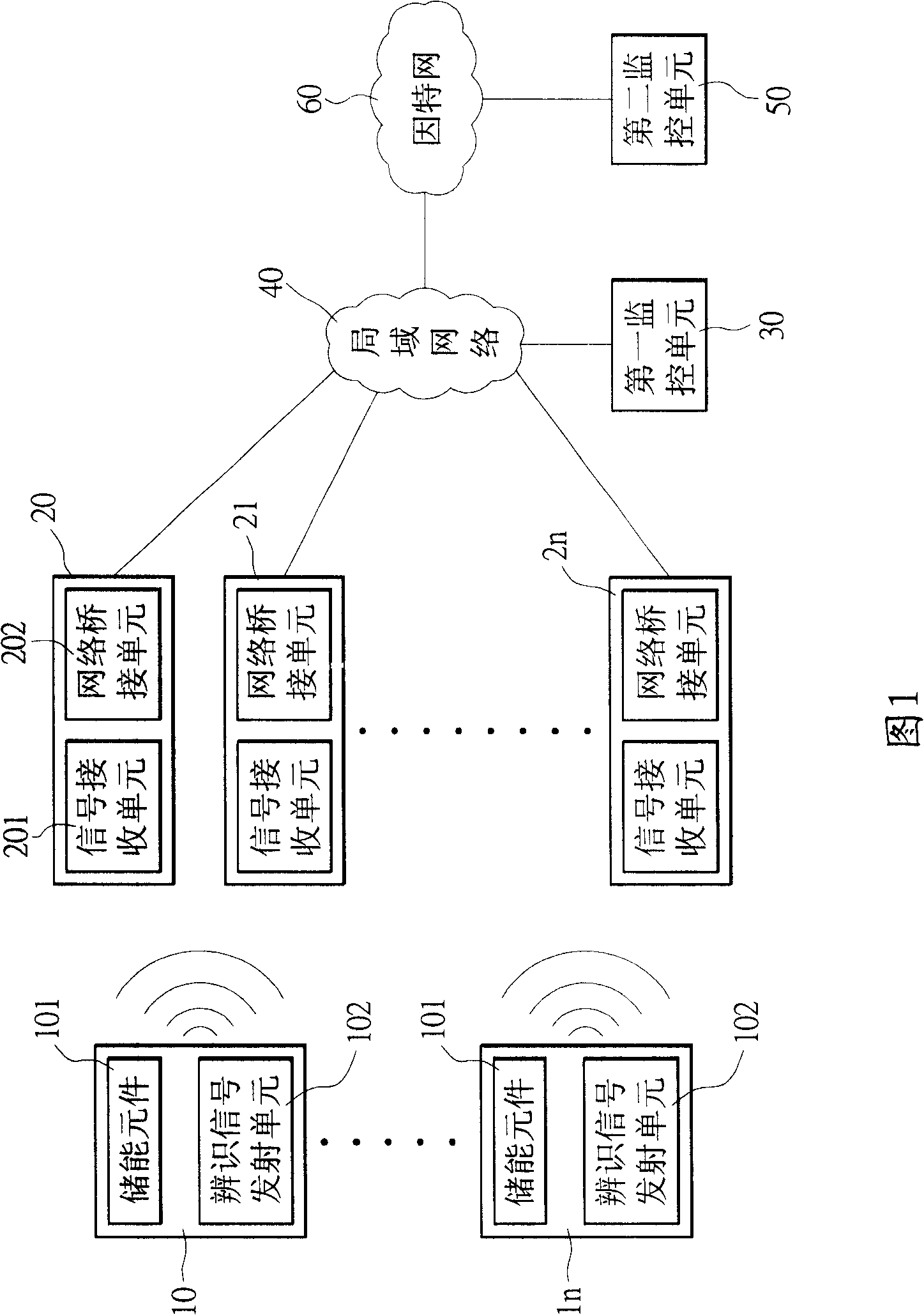
[0029] Please refer to FIG. 1 , which is a structure diagram of the location monitoring system of the present invention. The structure of the position monitoring system of the present invention includes a plurality of signal transmitting modules 10...1n, a plurality of signal detection modules 20, 21...2n, a first monitoring unit 30, a local area network 40, a second monitoring unit 50 and the Internet 60. The signal transmitting modules 10...1n each include an energy storage element 101 (such as a battery) and an identification signal transmitting unit 102, and the energy storage element 101 provides the power required for the identification signal transmitting unit 102 to transmit an identification signal; The way in which the signal transmitting modules 10 . . . 1n transmit the identification signal is not limited to real time (real time) or periodic output (send once in a period of time). The identification signals transmitted by each signal transmitting module 10...1n ar...


PUM


Abstract

A position monitoring system comprises at least one signal transmitting module, a plurality of signal detecting modules and a monitoring unit. The signal detecting modules are connected by local network and the monitoring unit is connected with the signal detecting modules by a local network or internet. The signal detecting modules are laid at an area to detect. An identification signal of signal transmitting module is detected by the signal detecting module, therefore the monitoring unit detects and records the position of the signal transmitting module. The position monitoring system has simple construction, can easily conquer the limit of a variety of environment, with lower cost than that of general monitoring system.

Description

technical field [0001] The invention relates to a position monitoring system, in particular to a position monitoring system for detecting the position of an object to be measured. Background technique [0002] Various monitoring systems have been popularized in our daily life. For example, in order to locate or track the location of the current vehicle, a global positioning system (Global Positioning System, GPS) is installed for monitoring. Or climbers also use GPS devices to locate in order to prevent getting lost or suffering, so that rescuers can know the correct location for rescue. In addition, it is not difficult to find that surveillance cameras are used to monitor the surrounding environment in various places, whether it is streets, public places, companies or stores, whether it is for crime prevention, tracing, monitoring, etc. [0003] However, although GPS systems and devices can use satellite positioning to track the correct location, they cannot continue to tr...

Claims


Application Information

Patent Timeline
Patent Type & Authority Applications(China)
IPC IPC(8): G01S5/08
Inventor 黄鋕铭
Owner EVERMORE TECH
Why Eureka
Try Eureka