Generator

A generator and electric power technology, applied in the direction of unipolar motors, electrical components, electromechanical devices, etc., can solve the problems of reduced rotational force of the rotor plate, reduced power generation efficiency, and power extraction, and achieve the effect of preventing the reduction of rotational force

Inactive Publication Date: 2008-08-20
冈本 范政 +1
View PDF1 Cites 3 Cited by
  • Summary
  • Abstract
  • Description
  • Claims
  • Application Information

AI Technical Summary

Problems solved by technology

Therefore, when the power is taken out from the winding (L1) to the winding (L6) of the annular winding (L1) to the winding (L12) of the annular core (11) of the stator (10), there is a possibility that the electric power cannot be obtained from the winding (L7) to the winding (L12) ) to take out the power problem
[0007] In addition, in order to eliminate the anti-phase electromotive force, it is necessary to set the Hall sensor (12), the first triac (T1) and the second triac (T2), which will generate a circuit load
In addition, since the electromotive force generated in winding (L1) ~ winding (L6) and winding (L7) ~ winding (L12) is in antiphase, the electromotive force is generated in winding (L1) ~ winding (L6) and winding (L7) ~ The magnetic field generated in the winding (L12) is also reversed, so a leakage magnetic field will be generated from the winding, resulting in a decrease in the rotational force of the rotor plate, thereby reducing the power generation efficiency

Method used


Image

  • Generator
  • Generator
  • Generator

Examples


Embodiment Construction

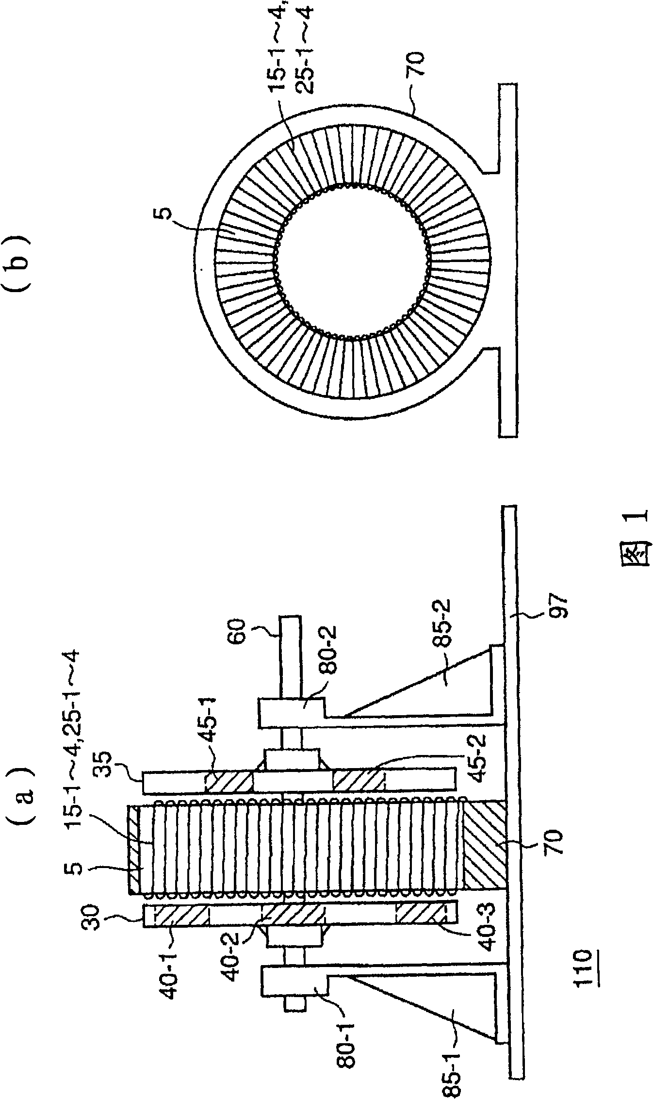
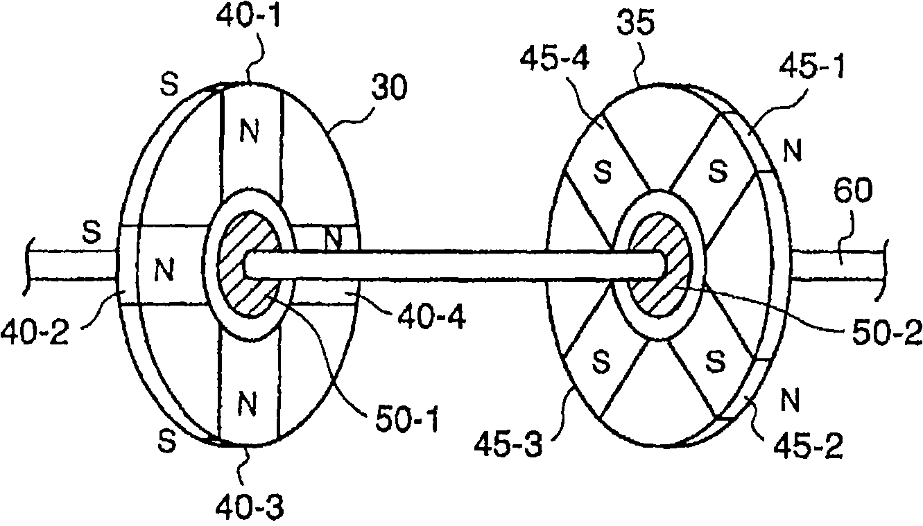
[0023] Hereinafter, embodiments of the present invention will be described with reference to the drawings. FIG. 1 is a configuration diagram showing the configuration of a generator according to the present invention. In (a) of FIG. 1, the stator 70 of the generator 110 is fixed on the base 97, and the annular core 5 is installed on the On the stator 70. The first rotor plate 30 and the second rotor plate 35 are arranged on bearings 80-1, 80-2 respectively having supporting plates 85-1, 85-2 through the drive shaft 60, and the bearings 80-1, 80-2 are fixed on on the base 97. In addition, the first rotor plate 30 and the second rotor plate 35 have first permanent magnets 40-1 to 4 and second permanent magnets 45-1 to 4, respectively. The drive shaft 60 receives a rotational drive torque (not shown) from the outside to rotate the first rotor plate 30 and the second rotor plate 35 to generate a rotating magnetic field.

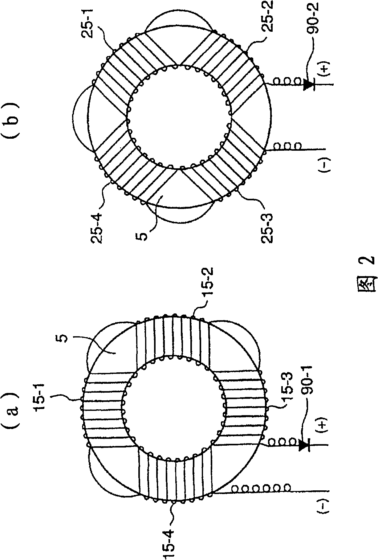
[0024] In (b) of FIG. 1 , the annular core 5 on which t...


PUM


Abstract

A high efficiency generator free from any burden on the circuit in which electromotive force is generated in the same direction for all windings, and a fall in the torque of a rotor disc due to leakage magnetic field from the winding is prevented by preventing generation of leakage magnetic field from the winding. The generator comprises first windings (15-1 to 15-4) wound around a fixed ringlike core (5) while being split as a plurality of segments, second windings (25-1 to 25-4) wound to cover the gaps between the first split windings while being split as the same number of segments as those of the first windings, and first and second rotor discs (30, 35) disposed oppositely to the respective opposite sides of the ringlike core (5). The first rotor disc has first permanent magnets (40-1 to 40-4) opposing the first windings, the second rotor disc has second permanent magnets (45-1 to 45-4) opposing the second windings, and power generated in the first and second windings (15-1 to 15-4, 25-1 to 25-4) through the rotation of the first and second rotor discs (30, 35) is taken out.

Description

technical field [0001] The present invention relates to a generator that generates electricity by rotating a permanent magnet using a rotational force applied from the outside. A generator that reduces the rotational force of the plates to improve power generation efficiency. Background technique [0002] Patent Document 1 describes a power generator that rotates a permanent magnet using a rotational force applied from the outside to generate power. In (a) of FIG. 7 , the power generating device (100) has a left rotor plate (5L) and a right rotor plate (5R) on both sides of a stator (10) held by a stator case (20). The N pole of the semicircular permanent magnet (6NL) magnetized in the direction opposite to the stator (10) faces the stator (10), and the permanent magnet (6NL) is joined to the left rotor plate (5L) . The S pole of the semicircular permanent magnet (6SL) magnetized in the direction opposite to the stator (10) faces the stator (10), and the permanent magnet ...

Claims


Application Information

Patent Timeline
Patent Type & Authority Applications(China)
IPC IPC(8): H02K16/02
CPCH02K21/24H02K31/00H02K16/02
Inventor 冈本哲夫
Owner 冈本 范政
Why Eureka
Try Eureka