Switching device with spring device for a change speed gearbox

A technology of shifting device and spring device, applied to components with teeth, transmission device control, belt/chain/gear, etc., which can solve the deviation of bolt manufacturing tolerances from each other, the existence of play, and the inaccurate positioning of the main shift shaft And other issues

Active Publication Date: 2008-08-13
GETRAG FORD TRANSMISSIONS GMBH
View PDF1 Cites 5 Cited by
  • Summary
  • Abstract
  • Description
  • Claims
  • Application Information

AI Technical Summary

Problems solved by technology

Therefore, the diameters of bolt and pin may deviate from each other due to manufacturing tolerances
Furthermore, the two torsion arms of the torsion spring may not run parallel to each other, which leads to play in th

Method used


Image

  • Switching device with spring device for a change speed gearbox
  • Switching device with spring device for a change speed gearbox
  • Switching device with spring device for a change speed gearbox

Examples


Embodiment Construction

[0030] figure 1 A typical shift diagram of a manual selector lever for shifting a manual transmission with six forward gears I to VI and one reverse gear R is shown. The forward gears I, II are located in the first shift gate 1 here. Correspondingly, the forward gears III and IV can be allocated to the second shift slot 2 , and the forward gears V and VI can be allocated to the third shift slot 3 . The reverse gear R can be reached via the shift gate 4 . The shift gates 1 , 2 , 3 , 4 are connected to each other by a selector gate 5 . The neutral position N is located in the intersection of the selector gate 5 and the shift gate 2 between the forward gears III, IV. A restoring force acts on the manual selector lever along the selector gate 5 , so that it can slide into the neutral position N as long as no force is applied from the outside.

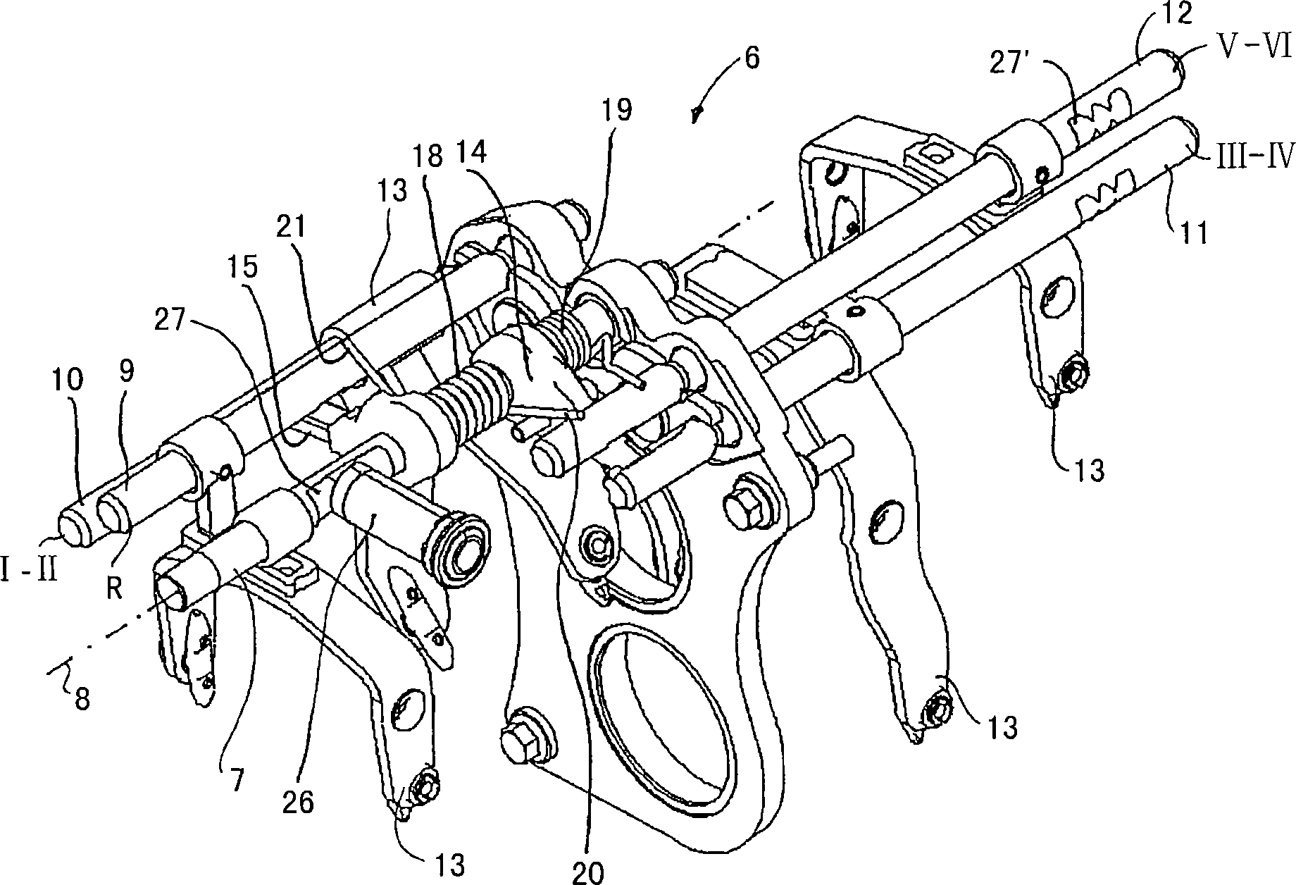
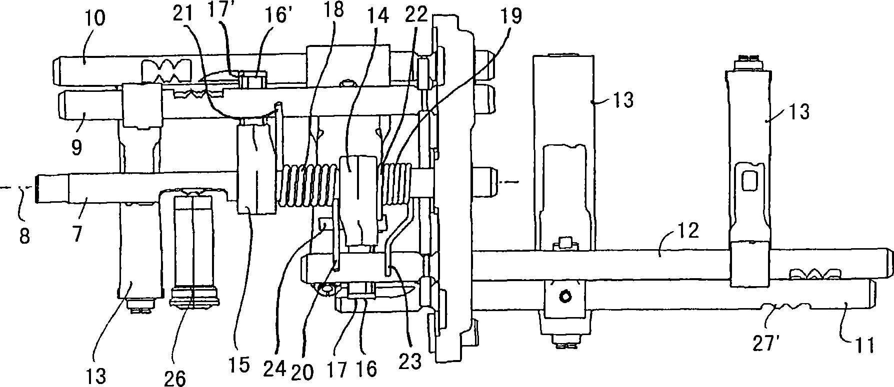
[0031] figure 1 The shift diagram shown in the figure 2 Corresponds to the shifting device 6 shown in FIG. 7 . figure 2 FIG. 7 sh...


PUM


Abstract

The shifting device has a main shifting shaft (7) which is axially displaceable and rotatable around an axis (8), and a shifting finger (14,15).The spring unit has a leg spring (18) and a spring element (19) and the leg (20) of the leg spring serves as a stopper. The spring element presses the main shifting shaft in a neutral position against the stopper.

Description

technical field [0001] The invention relates to a shifting device for a transmission having a main shifting shaft, axially displaceable shift fork shafts and a spring arrangement, the main shifting shaft being axially displaceable , can rotate about its axis and has at least one shift paddle, the main shift shaft can be coupled with these shift fork shafts through the shift paddle, so that the shift fork shaft can be connected by means of the main shift shaft To move, the spring device resists the rotation of the main shift shaft from the neutral position N. Background technique [0002] Such a shifting device is known, for example, from DE 29 35 590 C2. A transmission with five forward gears and one reverse gear can be operated via the gearshift there. By turning the main shift shaft, the connection to one of the shift fork shafts is established via the shift paddles. By axially moving the main shift shaft and correspondingly axially moving the shift fork shaft connected...

Claims


Application Information

Patent Timeline
IPC IPC(8): F16H59/04F16H63/30
CPCF16H63/20F16H2063/208F16H2059/0295
Inventor S・达尔德鲁普T・博格舒尔特R・特苏恩
Owner GETRAG FORD TRANSMISSIONS GMBH
Why Eureka
Try Eureka