Two-part oil scraper ring for internal combustion engines

A technology for oil scraping rings and internal combustion engines, applied to piston rings, mechanical equipment, engine components, etc., can solve problems such as insufficient oil scraping effect and structural height that can no longer be realized

Inactive Publication Date: 2008-08-06
MAHLE INT GMBH
View PDF2 Cites 1 Cited by
  • Summary
  • Abstract
  • Description
  • Claims
  • Application Information

AI Technical Summary

Problems solved by technology

Therefore, a reduction of the structural height to 1.5 mm or less leads to an insufficient oil scraping effect, as also described in DE 197

Method used


Image

  • Two-part oil scraper ring for internal combustion engines
  • Two-part oil scraper ring for internal combustion engines

Examples


Embodiment Construction

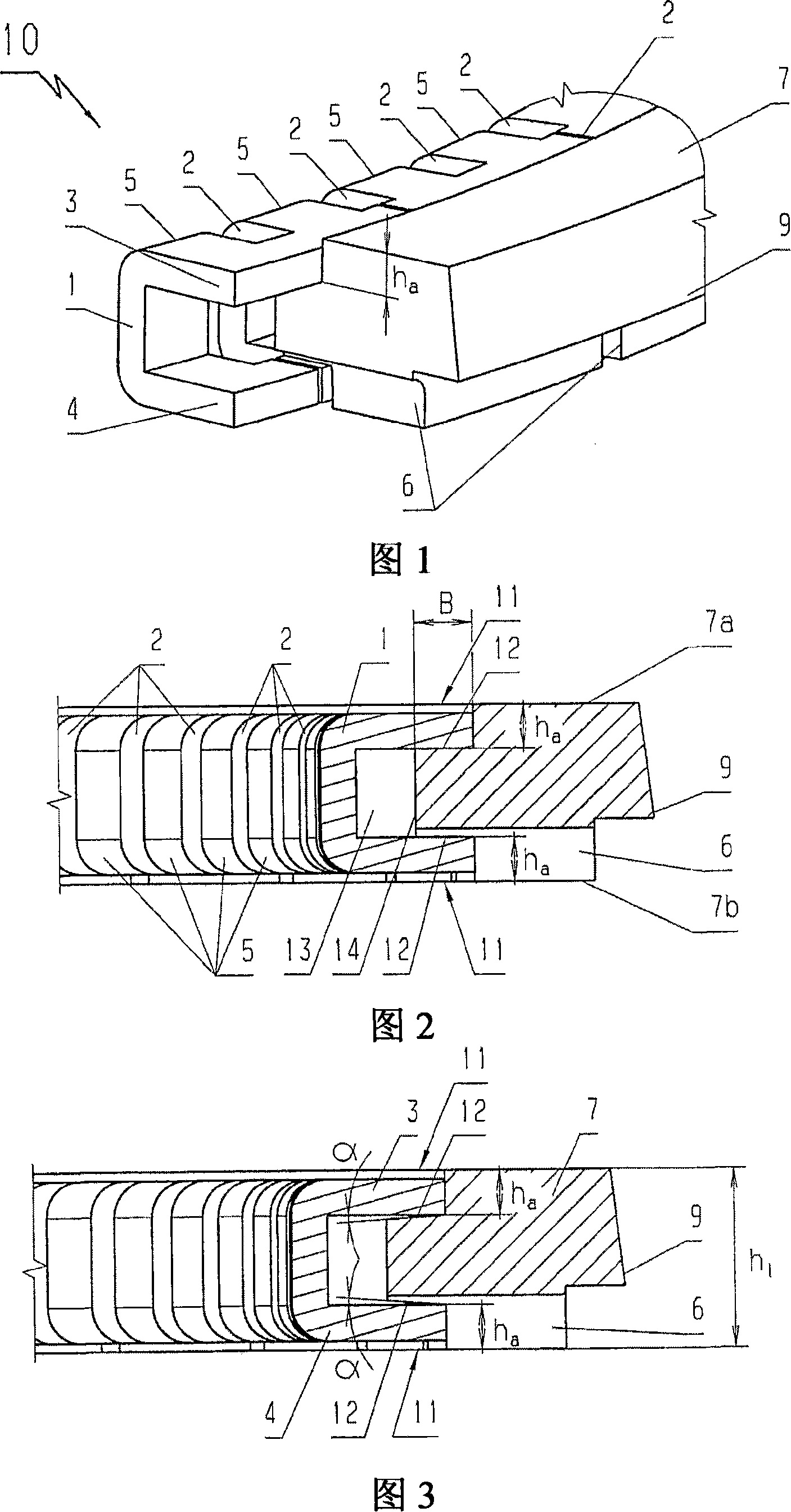
[0011] As can be seen from the perspective view of FIG. 1 , the oil wiper ring 10 according to the invention consists of an expanded spring ring 1 with a U-shaped cross-section, the ring body being arranged between elastic legs 3 and 4 pointing radially outwards of the expanded spring ring. 7. The ring body has a working surface 9. The expansion spring ring 1 has a cutout 2 on its radial inner side, so that the spring legs 3 and 4 are connected to one another via a web 5 designed as the back of the spring ring. Via these cutouts 2 the expansion spring ring 1 is designed elastically in the circumferential direction.

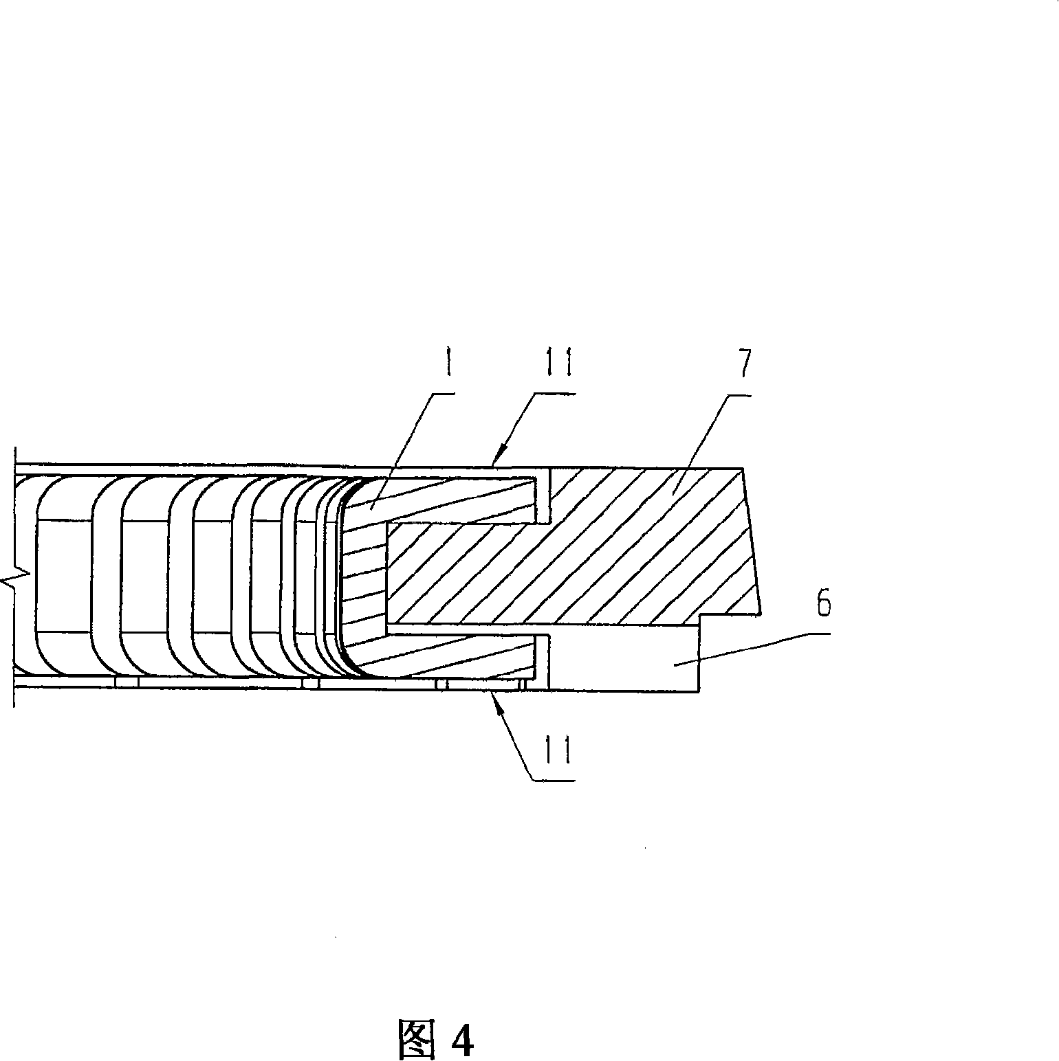
[0012] The ring body 7 , which can be designed as a nose-shaped conical ring, consists of steel or cast iron, and has sides 7 a and 7 b that are parallel to each other. These sides have a roughness of Rz<2 μm for steel ring bodies and Rz<4 μm for cast iron ring bodies. According to FIGS. 2 and 3 , the ring body 7 has at its radially inner end, that is to say in ...


PUM


Abstract

A two-part oil wiper ring (10) for an internal combustion engine comprises a U-shaped expanding spring ring (1) with an axial cutout (2) to form elastic legs (3, 4) pointing radially outwards, the two The spring legs are connected to each other via radially inner webs (5) and comprise a ring body (7) with parallel side faces (7a, 7b) and a running surface (9). In such an oil wiper ring, a minimum axial construction height is to be achieved with an improved oil wiper effect in that the side faces (7a, 7b) of the ring body have recesses (11) in their radially inner walls , these notches have bearing surfaces (12) for engaging the spring legs (3, 4) of the expansion spring ring, and are shaped such that the nominal height of the wiper ring is determined solely by the height of the ring body (7).

Description

technical field [0001] The invention relates to a two-part oil wiper ring for an internal combustion engine, comprising a U-shaped expanding spring ring with an axial cutout to form elastic legs pointing radially outwards, and a spring ring with respectively parallel sides and A running surface ring body, which is arranged between the spring legs, wherein only the ring body is in contact with the cylinder wall in the assembled state. Background technique [0002] DE 197 04 754 C1 discloses a two-part oil wiper ring with a U-shaped expansion spring ring. The single oil wiper blade arranged between the spring legs of the expansion spring ring allows an overall height of the oil wiper ring of approximately 1.5 mm. Compared with other known two-part oil wiper rings, for example known from DE 27 11 018 C2, this solution has the advantage that just enough tangential force is exerted on the wiper blade by means of the expansion spring , so that the oil-shaving effect is likewise ...

Claims


Application Information

Patent Timeline
IPC IPC(8): F16J9/06
CPCF16J9/06F16J9/069
Inventor 米夏埃尔·胡梅尔亚历山德罗斯·米祖格罗
Owner MAHLE INT GMBH
Why Eureka
Try Eureka