Tension bolt for compressor

A technology for tightening bolts and turbo compressors, used in mechanical equipment, machines/engines, liquid fuel engines, etc., can solve problems such as low operating efficiency and small elongation of tightening bolts, and achieve improved workability and dangerous speed. It does not reduce the effect of simplifying the adjustment work

Active Publication Date: 2008-08-06
IHI ROTATING MACHINERY ENG CO LTD
View PDF2 Cites 4 Cited by
  • Summary
  • Abstract
  • Description
  • Claims
  • Application Information

AI Technical Summary

Problems solved by technology

[0006] However, since the elongation of the tension bolt is extremely small, it is necessary to perform repeated operations many times in order to obtain the target elongation, resulting in a problem of low working efficiency.

Method used


Image

  • Tension bolt for compressor
  • Tension bolt for compressor
  • Tension bolt for compressor

Examples


no. 2 approach

[0087] 6A is a cross-sectional view of the fastening mechanism 90 of the second embodiment, and FIG. 6B is a cross-sectional view of the first impeller 21.

[0088] As with the fastening mechanism 70 of the first embodiment, the fastening mechanism 90 fastens both ends of the second rotating shaft 12 to the first impeller 21 and the second impeller 22.

[0089] Hereinafter, only the parts different from the fastening mechanism 70 of the first embodiment will be described, and the same parts are denoted by the same reference numerals, and the description thereof will be omitted.

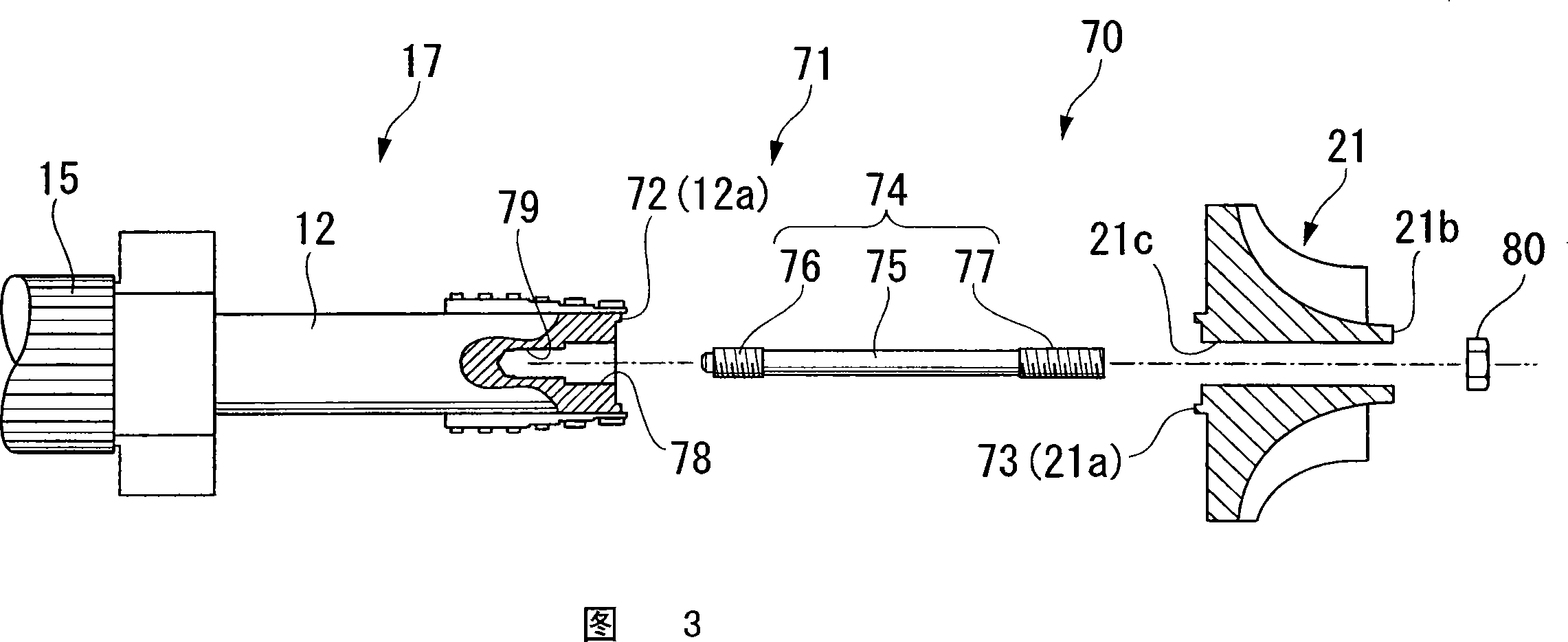
[0090] The fastening mechanism 90 includes: a curved tooth coupling 71, which fastens the second rotating shaft 12 and the first impeller 21 in a consistent manner with their respective rotating shaft cores; and a tension bolt 74, which clamps and presses at a predetermined pressure Support the second rotating shaft 12 and the first impeller 21; tighten the nut 80 and so on.

[0091]The arc tooth coupling...


PUM


Abstract

The invention relates to a rotor (17) of a turbocompressor consisting of an impeller (21) and a rotating shaft (12) supporting the impeller (21), having a fastening mechanism (70) comprising : a mechanical coupling (71), formed on the respective end faces of the impeller (21) and the rotating shaft (12); a tension bolt (74), inserted into a through hole formed in the rotation center of the impeller (21); The fastening nut (80) is screwed with the first external thread (77) formed on one end of the tension bolt (74); the receiving hole (78) is formed on the end surface of the rotating shaft (12) to receive the tension bolt (74) ) part of the extension (75); the internal thread (79) is formed on the bottom surface of the receiving hole (78), and is screwed with the second external thread (76) formed on the other end of the tension bolt (74). According to the present invention, it is possible to increase the elongation of the tie bolts, thereby improving the efficiency and stabilization of the joining operation.

Description

Technical field [0001] The invention relates to a tension bolt for a compressor. This application claims priority based on Japanese Patent Application No. 2006-318822 filed on November 27, 2006, and the content is cited here. Background technique [0002] As an industrial turbo compressor, a turbo compressor that compresses air or the like in multiple stages is known. In this turbo compressor, the rotating shaft to which the impeller is connected is rotated by a drive motor via a gear train. [0003] There are cases where the impeller is connected to only one end of the rotating shaft, or the impeller is connected to both ends of the rotating shaft, or there are a plurality of such rotating shafts. In either case, the coupling that combines the rotating shaft and the impeller uses a curved tooth coupling. A tightening bolt is used in the fastening mechanism of the coupling. The axial force of the tightening bolt generates a large pushing force on the arc tooth coupling that conne...

Claims


Application Information

Patent Timeline
IPC IPC(8): F04D29/28F16D1/06
CPCF04D25/163F04D29/266F16D1/076
Inventor 河田真广若林拓也小野海士前田智久
Owner IHI ROTATING MACHINERY ENG CO LTD
Why Eureka
Try Eureka