Correcting for image distortion in image projectors

An image and projection technology, applied in image communication, equipment, color TV components, etc., can solve problems such as image resolution degradation and loss

Inactive Publication Date: 2008-07-23
MICROVISION
View PDF1 Cites 8 Cited by
  • Summary
  • Abstract
  • Description
  • Claims
  • Application Information

AI Technical Summary

Problems solved by technology

However, when doing so, the image resolution drops due to the loss of usable pixels

Method used


Image

  • Correcting for image distortion in image projectors
  • Correcting for image distortion in image projectors
  • Correcting for image distortion in image projectors

Examples


Embodiment Construction

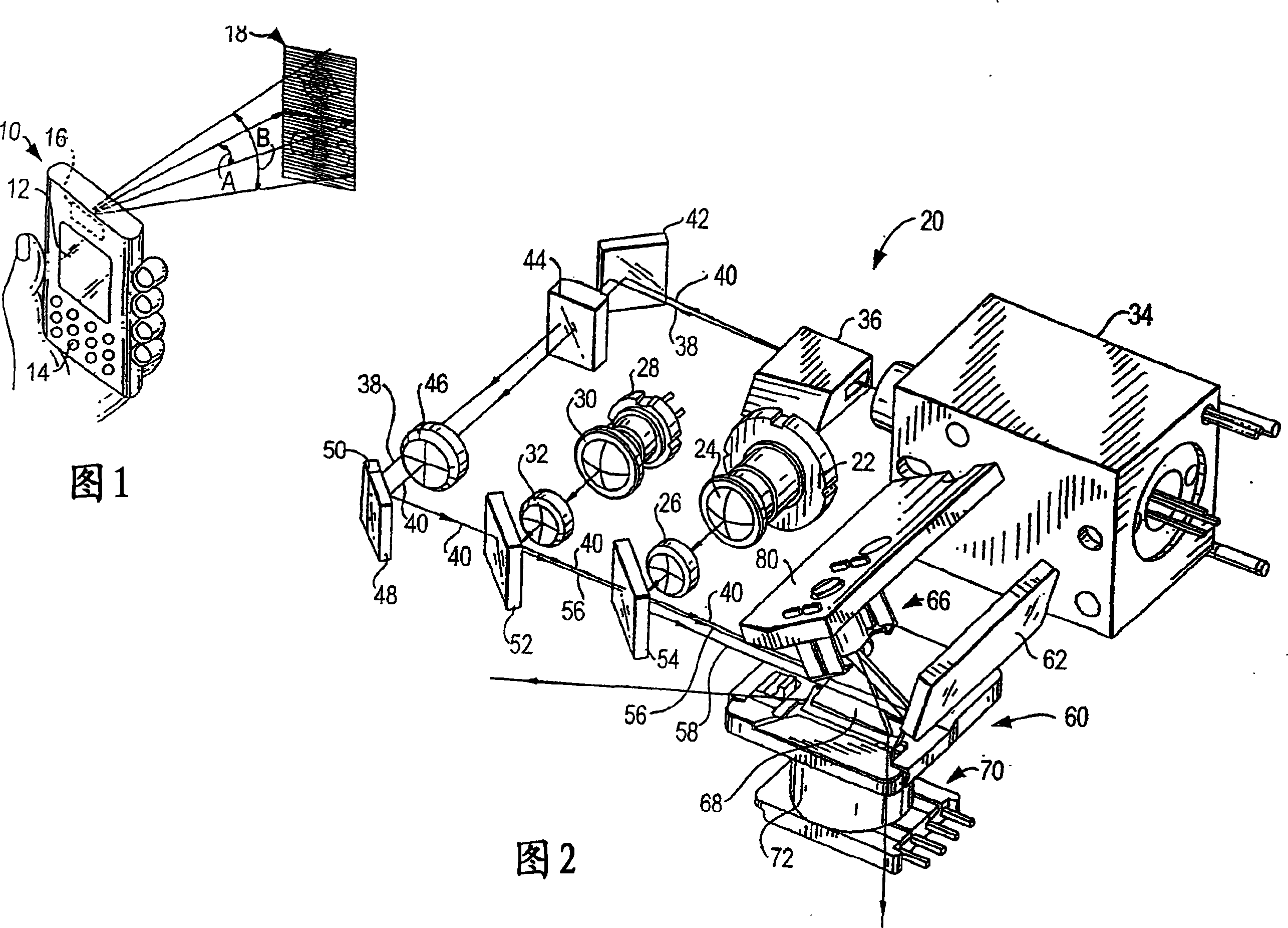
[0024] Reference numeral 10 in FIG. 1 generally identifies a hand-held device, such as a personal digital assistant, in which is mounted a light-weight, compact image projection arrangement 20 as shown in FIG. A two-dimensional color distortion-free image is projected at a variable distance from the device. As an example, image 18 is located within a working range of distance relative to device 10 .

[0025] As shown in FIG. 1 , the undistorted image 18 extends within an optical horizontal scan angle A of the image extending in the horizontal direction and within an optical vertical scan angle B extending in the vertical direction. As described below, the image consists of illuminated and unilluminated pixels on a raster pattern of scan lines swept out by the scanner in arrangement 20 .

[0026] The parallelepiped shape of the device 10 represents only one form factor of the housing in which the arrangement 20 can be realized. The device can be shaped as a pen, a cell phone,...


PUM


Abstract

An arrangement for, and a method of, correcting for image distortion in an image projection system include making the scan lines of the projected image all of the same length by adjusting the amplitude of a drive signal used to sweep a laser beam to form each scan line of the image.

Description

technical field [0001] The present invention relates generally to projecting images onto a projection surface, such as a screen, and more particularly to correcting distortions of such images. Background technique [0002] It is known to project a two-dimensional image onto a projection surface, such as a screen, based on oscillating a pair of scanning mirrors in mutually perpendicular directions to sweep a laser beam out of a raster pattern of scan lines. However, known image projection systems project images with limited resolution (typically less than a quarter of the quality of a Video Graphics Array (VGA) of 640 x 480 pixels) and are determined primarily by the orientation of the screen relative to the image projection system Causes some image distortion. [0003] For example, when an image having a square or rectangular image area is projected onto a tilted screen that is tilted relative to the optical axis along which the image is projected, the projected image suffe...

Claims


Application Information

Patent Timeline
Patent Type & Authority Applications(China)
IPC IPC(8): G02B26/08
CPCH04N5/74G09G3/002H04N9/3129H04N9/3185
Inventor 弗雷德里克·F·伍德
Owner MICROVISION
Why Eureka
Try Eureka