Floor type air conditioner

An air conditioner, floor-standing technology, applied in air conditioning systems, heating methods, space heating and ventilation, etc., can solve problems such as strength reduction, wetting, component cost or installation cost increase, etc., to achieve easy operation, cost reduction, Create easy effects

Inactive Publication Date: 2008-07-23
SANYO ELECTRIC CO LTD
View PDF2 Cites 6 Cited by
  • Summary
  • Abstract
  • Description
  • Claims
  • Application Information

AI Technical Summary

Problems solved by technology

In particular, when the air discharge port is formed on the front surface of the front panel or the discharge grill unit, the strength of this part decreases.
When bending a metal plate, it is necessary to use a thick metal plate, or it is necessary to install a reinforcing material for reinforcement, etc. If a thick metal plate is used, there are problems of increased cost and inconvenient opening and closing or disassembly. Issues with increased component costs or installation costs
In addition, when molding with synthetic resin, thickening not only increases the molding cost, but also if thick reinforcing ribs are provided, pits are formed due to shrinkage cavities (しけ) during molding, so it is difficult to form a plane.
[0010] In addition, when the above-mentioned floor-standing air conditioner performs cooling operation, the cold air cooled by the heat exchanger collides with the front panel of Patent Document 1 or the discharge grill unit of Patent Document 2, and the air is blown on the back of the front panel or the discharge grill unit. Dew is generated on the back of the unit, and the dew flows down to wet the filter or other parts below, and may also wet the floor where the floor-standing air conditioner is installed

Method used


Image

  • Floor type air conditioner
  • Floor type air conditioner
  • Floor type air conditioner

Examples


Embodiment 1

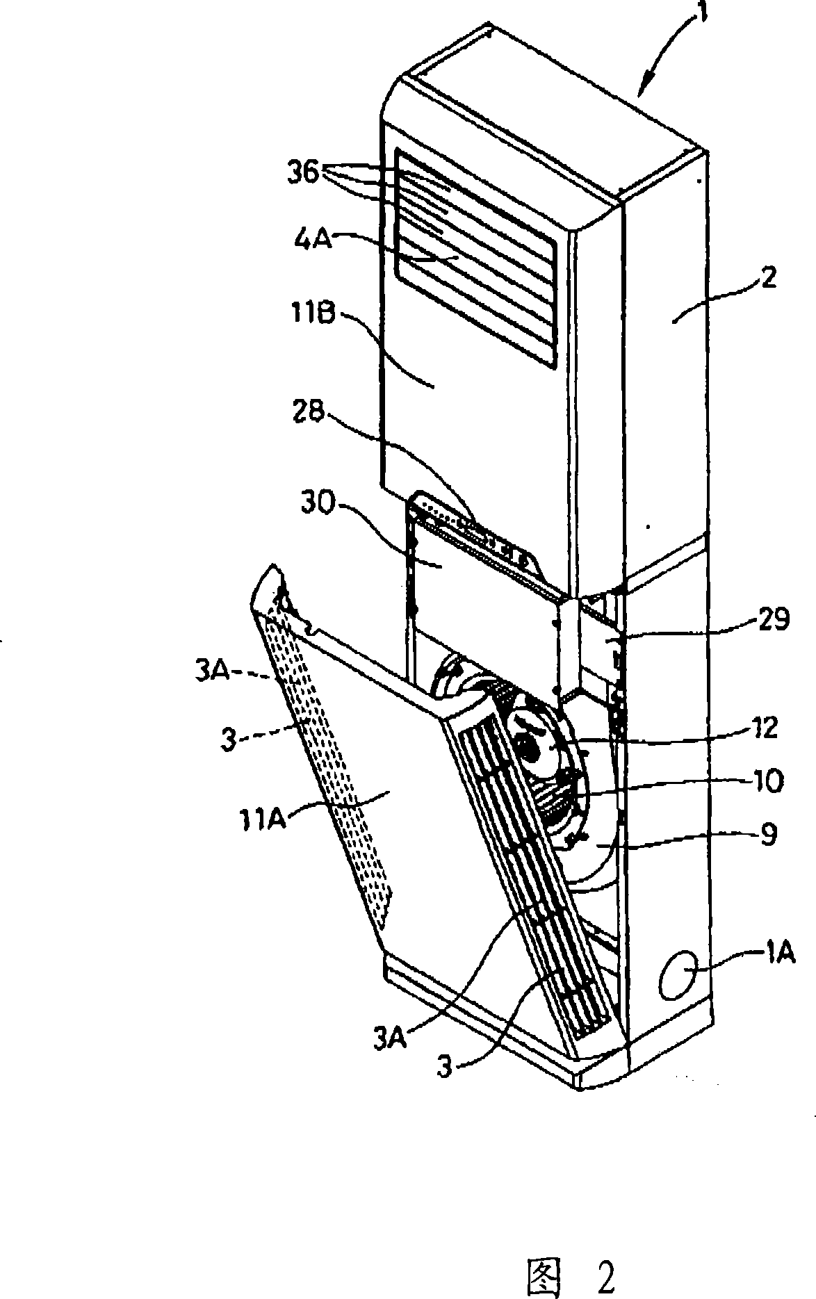
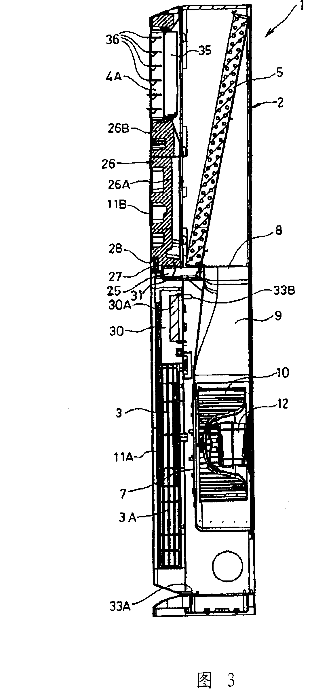
[0070] Next, Embodiment 1 of the present invention will be described. Fig. 1 is a perspective view illustrating the relationship between the floor-standing air conditioner of the present invention and the outdoor unit; Fig. 2 is a front perspective view with the lower front panel of the floor-standing air conditioner of the present invention opened; Fig. 3 is the C-C position of Fig. 1 Fig. 4 is a rear perspective view illustrating the relationship between the air supply device and the front panel of the floor-standing air conditioner of the present invention; Fig. 5 shows the partition of the upper front panel of the floor-standing air conditioner of the present invention The back perspective view under the state of thermal material; Fig. 6 is the sectional enlarged view of the D-D place of Fig. 1; Fig. 7 is the longitudinal sectional side view of the drain pan part illustrating the floor type air conditioner of the present invention; Fig. 8 is a representation of the present ...


PUM


Abstract

A floor type air conditioner is provided. The air from the air absorption inlet is exhausted from the front air blowout outlet. A front panel is shaped by bending the metal plate or shaping the synthetic resin, the air blowout outlet is formed before the front panel, thus the intension thereof is reduced. In addition, when the refrigeration is performed, the cool air cooled at the heat exchanger collides the front panel and the dew is generated on the front panel to damp the inferior filter or the other parts. In order to solve the above problem, the front panel is divided into upper front panel and lower front panel, and the lower end of the heat exchanger opens towards the top of the drain plate, moreover the foaming heat protecting material such as foaming styrol is pasted on almost the back of the front panel in way of encircling the air blowout outlet and the lower part of the foaming heat protecting material opens towards the top of the drain plate.

Description

technical field [0001] The invention relates to a floor-standing air conditioner, which is equipped with a heat exchanger and a blower on the air path from the air sucked in from the air inlet to the air outlet, and the blower is used to blow the air sucked in from the air inlet. The air is sent to the heat exchanger. Background technique [0002] A floor type air conditioner has: a suction grille, which is arranged on the lower part of the front panel of the floor type air conditioner body; a casing, which makes the air inlet face the suction grille and is arranged in the body; a multi-blade fan ( シッツクフアン), which is installed in the casing (the blower is composed of the casing, the multi-blade fan, and the fan motor); the heat exchanger, whose upper part is inclined backward relative to the lower part, is arranged above the blower outlet of the blower ; the air outlet, which is provided at the front upper part of the main body in order to send the air which has exchanged he...

Claims


Application Information

Patent Timeline
IPC IPC(8): F24F1/00F24F13/20F24F13/22
Inventor 金子好章中岛宪一
Owner SANYO ELECTRIC CO LTD
Why Eureka
Try Eureka