Lock for vehicle parking position
A technology for parking locks and lock housings, which is applied in electric bicycles and motorcycle parking locks, and in the field of bicycles. It can solve the problems of many structural transmission parts, disorderly placement of bicycles, and complicated movement transmission, and achieves convenient access to vehicles and a stable structure. Simple, good anti-theft performance
- Summary
- Abstract
- Description
- Claims
- Application Information
AI Technical Summary
Problems solved by technology
Method used
Image
Examples
Embodiment 1
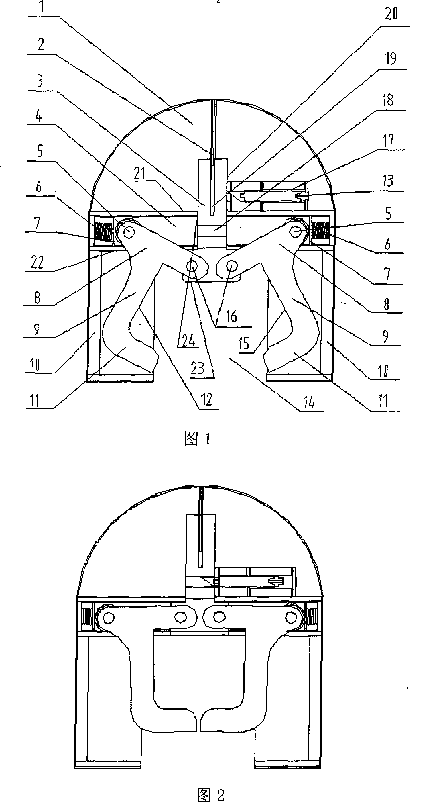
[0022] A parking lock shown in Fig. 1 comprises a lock case 1 and a lock control device, one end of the lock case 1 is a notch 14, the upper part of the notch of the lock case is provided with a transverse groove rail 4, and the back portion 21 of the transverse groove rail is provided with a hole 24, The notch 22 of the transverse groove rail faces the notch 14 of the lock case; the lock control device includes a lock bar 3, a pair of T-shaped lock plates 12 and 15 that can be held together, a pin shaft 5 and an electric control lock 17, and the lock bar 3 passes through the lock case Hole 24 on the groove rail, there is a lock mouth groove 18 that is matched with the lock core 13 of electric control lock 17 on the lock bar 3, and the opposite end of the transverse arm part 8 of two lock plates 12,15 and lock bar 3 pass pin Axle 16 is movably connected, and the other end of the transverse arm part 8 of locking piece 12,15 is hingedly limited in the grooved track with the beari...
Embodiment 2
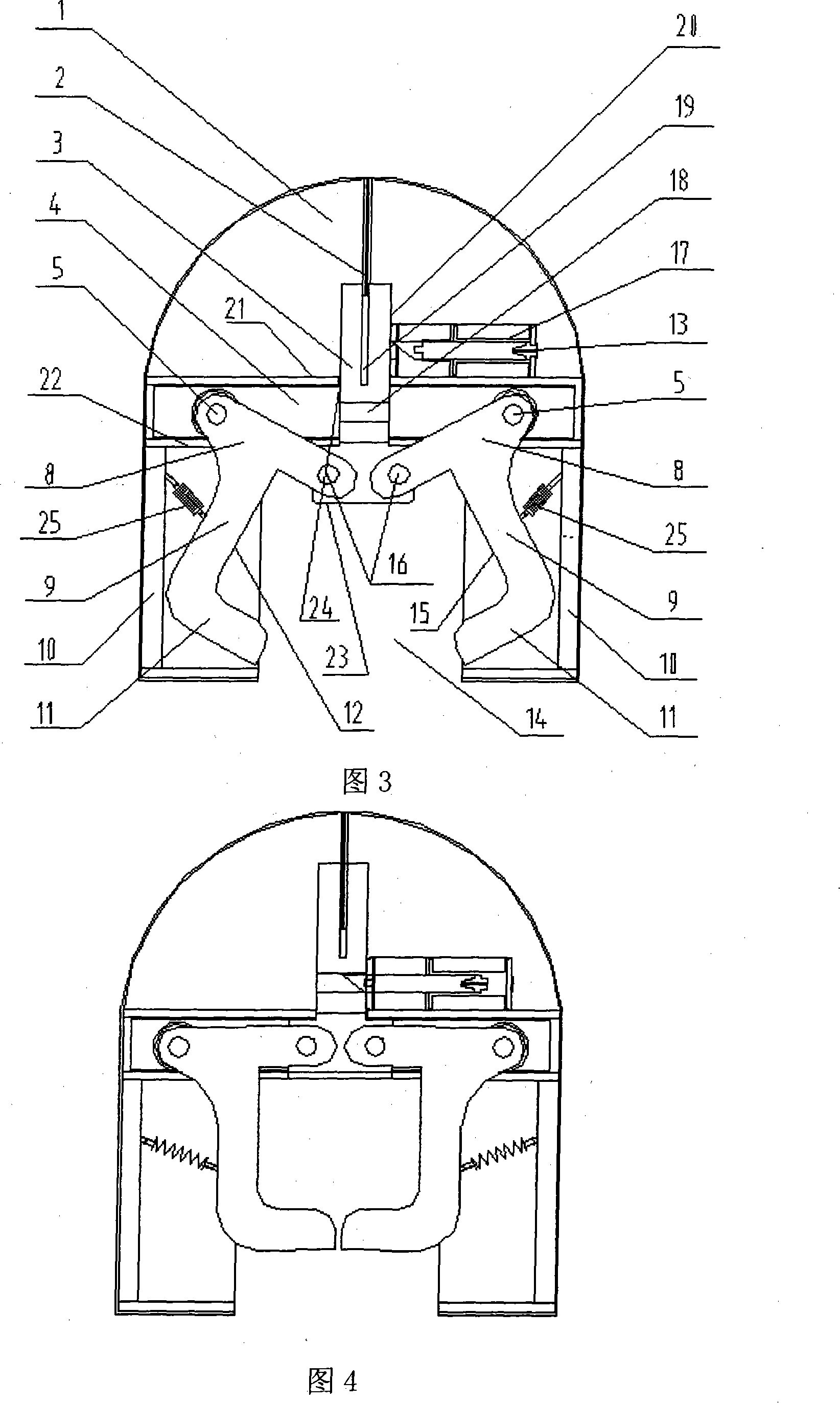
[0028] As shown in Figures 3-4, another structure of the present invention is that a tension spring 25 is arranged between the limit blocks 10 of the lock housing 1 near the two sides of the lock plate and the vertical bar part 9 of the lock plate to connect, when the parking lock When it is in the open state, the two extension springs 25 are in a free state. When the wheel pushes the lock bar 3 to move forward, the parking lock reaches the closed state. The action process of each part is the same as that of the lock structure shown in Fig. , when the two locking pieces 12, 15 rotate towards the middle relative to the two pin shafts 5, the two extension springs 25 are stretched by the cross arm portions 8 of the two locking pieces.
[0029] When the car is to be picked up, input power to the electric control lock 17, and the lock core 13 will extend the part in the locking groove 18 on the locking bar 3 to withdraw, and the wheel will withdraw from the gap 14 of the lock housin...
Embodiment 3
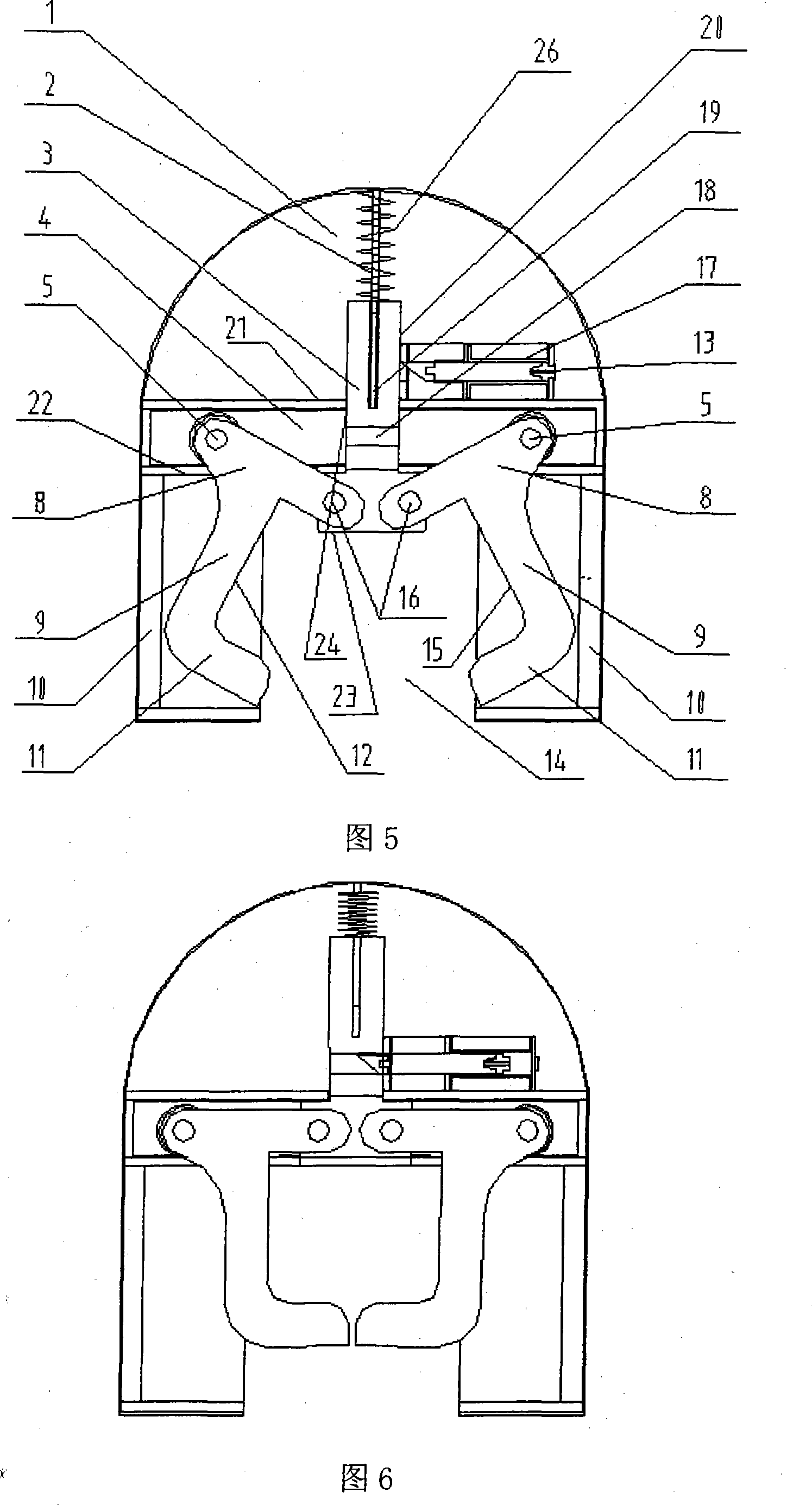
[0031]As shown in FIGS. 5-6 , in another structure of the present invention, a compression spring 27 is sleeved on the guide rod 2 on the lock case 1 . When the parking lock is in the open state, the compression spring 27 is in a free state. When the wheel pushes the lock bar 3 to move forward, the parking lock reaches the closed state. The action process of each part is the same as that of the lock structure shown in Fig. In the process of action, when the two locking pieces 12, 15 rotate towards the middle relative to the two pin shafts 5, the compression spring 27 is compressed by the lock lever 3 moving forward along the hole 24 at the back of the transverse groove rail 4 of the lock housing 1 , until a side 21 of the transverse grooved rail 4 blocks the transverse arm portion 8 of the lock plate and continues to move forward. At this time, the lock core 13 of the electric control lock 17 is close to the sharp corner of the lock bar 3 and just aligned with the lock bar 3. ...
PUM
 Abstract
Description
Claims
Application Information
 - R&D
- Intellectual Property
- Life Sciences
- Materials
- Tech Scout
- Unparalleled Data Quality
- Higher Quality Content
- 60% Fewer Hallucinations
Browse by: Latest US Patents, China's latest patents, Technical Efficacy Thesaurus, Application Domain, Technology Topic, Popular Technical Reports.
© 2025 PatSnap. All rights reserved.Legal|Privacy policy|Modern Slavery Act Transparency Statement|Sitemap|About US| Contact US: help@patsnap.com


