
Camshaft fixture cramp and its automatically printing method

A tooling fixture and camshaft technology, which is applied to printing devices, printing, typewriters, etc., can solve the problem that the camshaft cannot be used for error proofing, marking and scanning, etc., and achieves the effect of various varieties and convenient use.

Inactive Publication Date: 2008-07-02
上海亚太计算机信息系统有限公司
View PDF0 Cites 17 Cited by
  • Summary
  • Abstract
  • Description
  • Claims
  • Application Information

AI Technical Summary

Problems solved by technology

[0002] With the continuous expansion of the production of the automobile industry and the increasing number of models, the camshaft production line of the power plant has changed from a single camshaft product to multiple types and models. The previous camshaft printers can only print for a single product, and the camshaft cannot be used for error proofing. Disadvantages of marking and scanning

Method used


Image

  • Camshaft fixture cramp and its automatically printing method
  • Camshaft fixture cramp and its automatically printing method
  • Camshaft fixture cramp and its automatically printing method

Examples


Embodiment Construction

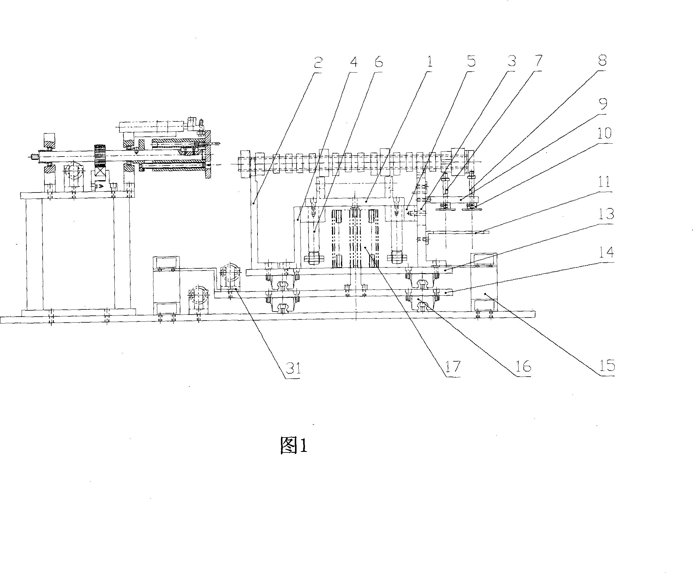
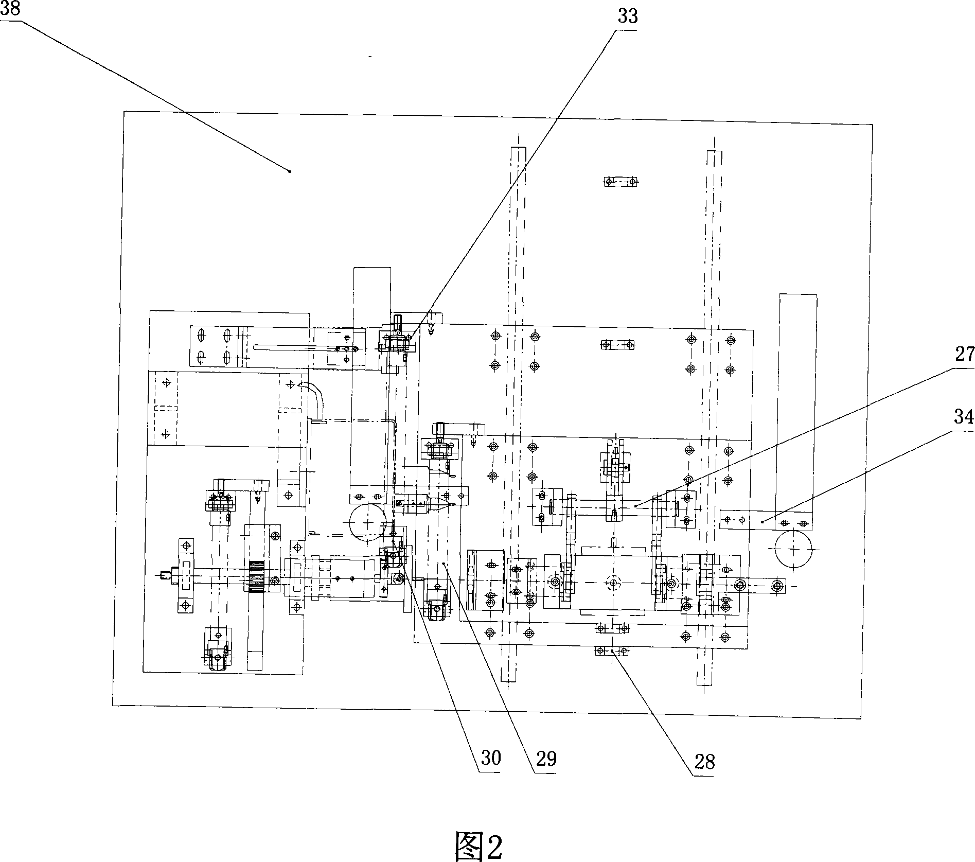
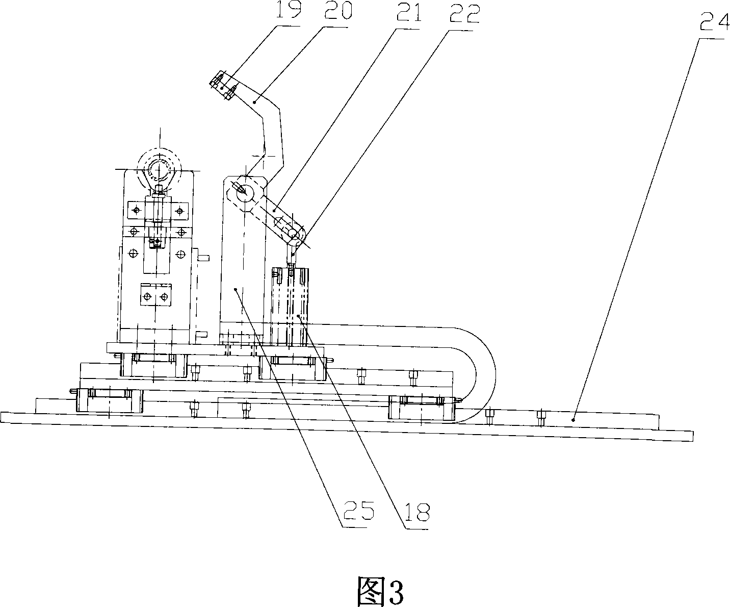
[0104] Referring to accompanying drawings 1, 2, 3, 4, and 5, the present invention can perform error-proofing, marking, and scanning for different camshafts. The relative positions of the 2 process holes on the end face of the camshaft and the cam are random, so when the cam is used for positioning, the positions of the 2 holes in the printing section are not fixed, and the steel needle printer must avoid the two holes when printing, otherwise the steel will be damaged. Needle printers, that's the key.

[0105] The device of the present invention is mainly composed of the hardware part of the camshaft marking system, including: tooling fixture, air supply device, pneumatic component box, electrical box, profile protection net and PANEL box parts. The tooling fixture is composed of a camshaft lifting mechanism, a thimble It consists of a pushing mechanism, a positioning mechanism, a camshaft rotating mechanism, a camshaft clamping mechanism, a printing position pushing mechanis...


PUM


Abstract

The invention relates to the automobile camshaft printer technique field, in particular to a camshaft clamp and an automatic printing method used for a camshaft product line of a power plant of the automobile field. The device mainly comprises a camshaft marking system and other hardware parts, comprising a work clamp, a gas supply device and a PANEL box, etc. The method is the automatic printing method used for the camshaft work clamp and mainly aims to solve the hardware part and to solve how to improve the work clamp. And a software part mainly solves the relevant technical problems about how to control a PLC, etc. The invention has the beneficial effects that the invention can carry out an anti-error, marking and scanning treatment for different camshafts. And corresponding positions between two process holes at end faces of the camshaft and the cam are random. When the cam for positioning is adopted, the positions of two holes at the printing end face are not fixed. The invention has the advantages that the use is convenient and the variety is various, etc.

Description

technical field [0001] The invention relates to the technical field of camshaft printers in the automobile industry, in particular to a camshaft fixture and an automatic printing method mainly used in a camshaft production line in a power workshop in the automobile industry. Background technique [0002] With the continuous expansion of the production of the automobile industry and the increasing number of models, the camshaft production line of the power plant has changed from a single camshaft product to multiple types and models. The previous camshaft printers can only print for a single product, and the camshaft cannot be used for error proofing. Marking and scanning and other shortcomings. Contents of the invention [0003] In order to overcome the above disadvantages, the main purpose of the present invention is to provide an automatic printing method through the tooling fixture, the air supply device and the camshaft tooling fixture to achieve error-proofing, markin...

Claims


Application Information

Patent Timeline
IPC IPC(8): B41J3/50B41J3/407B41J29/38B41J23/24B41J23/32B41J29/46
Inventor 陈剑峰罗坤李勇刚
Owner 上海亚太计算机信息系统有限公司
Learn More