
Pivot and shaft sleeve structure thereof

A pivot and shaft sleeve technology, applied in the field of pivot shaft and its shaft sleeve structure, can solve the problems of inconvenient maintenance, deformation of the shaft sleeve, time-consuming and laborious disassembly, etc.

Active Publication Date: 2011-09-14
SHANGHAI MUNICIPAL ELECTRIC POWER CO
View PDF0 Cites 0 Cited by
  • Summary
  • Abstract
  • Description
  • Claims
  • Application Information

AI Technical Summary

Problems solved by technology

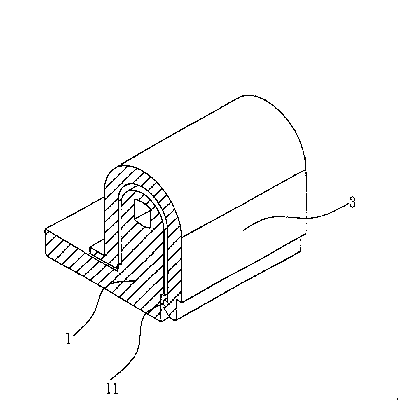
[0003] There are existing methods for fixing the aforementioned bushing to the pivot base, such as figure 1 As shown, in order to prevent the shaft sleeve 3 from falling off, the shaft sleeve 3 does not have any arm design for applying force, which makes the installation easy, but it is very difficult to open when maintenance is required. The shaft sleeve 3 engaged on the pivot base 1 can be slightly disengaged from the hook groove 11 designed by the pivot base 1 by pulling with the help of a tool, which not only makes disassembly and assembly inconvenient and time-consuming, but also requires tools Assisted but unable to achieve the effect of quick release and quick group
[0004] However, the existing methods have plagued the current maintenance needs. Considering that the ownership rate of notebook computers is getting higher and higher, the maintenance probability of old notebook computers has also increased a lot, especially for LCD The disassembly of the panel is the main point of replacement, which also greatly increases the demand for dismantling the pivot bushing. If the notebook computer still adopts the existing pivot and bushing structure design at this time, it will be time-consuming and laborious to disassemble, resulting in inconvenient maintenance. , if the tool is used to assist, it is not only troublesome but also easy to cause deformation of the shaft sleeve

Method used


Image

  • Pivot and shaft sleeve structure thereof
  • Pivot and shaft sleeve structure thereof
  • Pivot and shaft sleeve structure thereof

Examples


Embodiment Construction

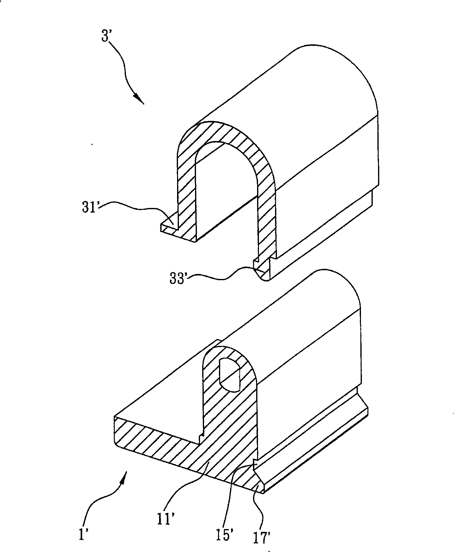
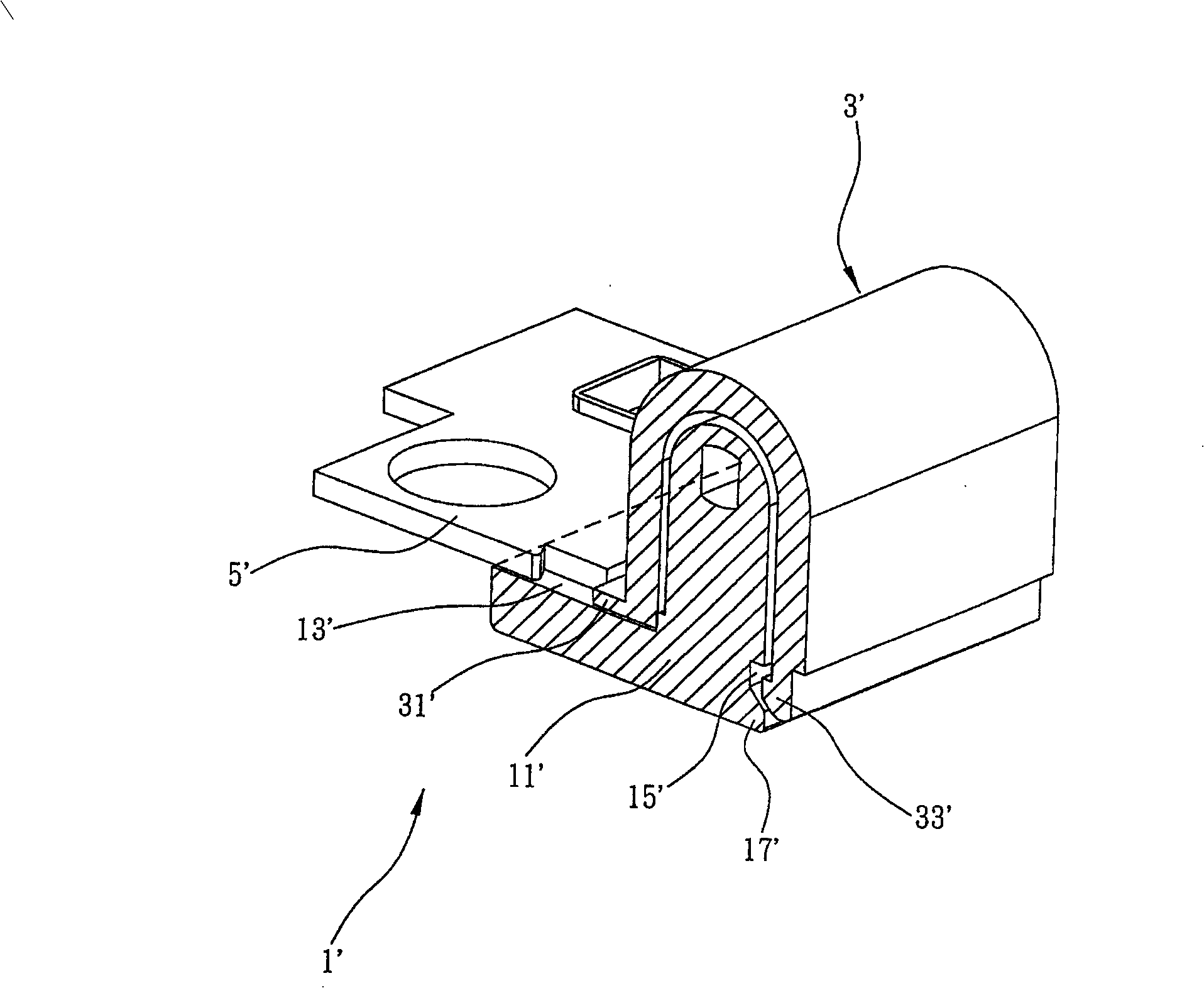
[0026] see figure 2 , which is a schematic diagram of an exploded view of the structure of the pivot and its bushing of the present invention, and then please match image 3 For reference, it is a sectional view of the assembly of the pivot shaft and its bushing structure of the present invention. As shown in the figure, the pivot shaft and its bushing structure of the present invention include a pivot base 1' and a bushing 3'. The pivot base 1' has a body 11' with a fixed pivot, and the body 11' is interposed with the main structure of the notebook computer 5' to form a first positioning part 13', and the position on the body 11' relative to the first positioning part 13' One side is provided with a second positioning part 15', and a convex part 17' is added below the second positioning part 15'; and the bushing 3' has a first positioning part 13' combined with the pivot base 1' The first engaging portion 31' and the second engaging portion 33' combined with the second posi...


PUM


Abstract

The invention discloses a pivot and a pivot sleeve structure thereof which are positioned by a locking pin on a frame provided with a first locating hole and a second locating hole for locking a bayonet baffle plate of a function extension card. The invention comprises a pivot base and a pivot sleeve. The top of the pivot sleeve being pressed, a grab of the pivot sleeve slide out of a grab groovepositioned on the pivot base under the guide a protruding block, thereby the pivot sleeve is easy to be detached form the pivot sleeve, without any assistant tool, thereby solving the problems existing in the prior art.

Description

technical field [0001] The present invention relates to a pivot structure, in more detail, relates to a pivot and its sleeve structure which is convenient to disassemble and can be operated without tools. Background technique [0002] In notebook computers, the liquid crystal panel and the main structure of the notebook computer are mostly connected by pivots to achieve the effect of fixing the positioning of the liquid crystal panel. In order to protect the pivot mechanism from damage, the notebook computer is usually placed above the pivot. A shaft sleeve is added, and the sleeve of this shaft sleeve is mostly assembled in a snap-fitting manner. [0003] There are existing methods for fixing the aforementioned bushing to the pivot base, such as figure 1 As shown, in order to prevent the shaft sleeve 3 from falling off, the shaft sleeve 3 does not have any arm design for applying force, which makes the installation easy, but it is very difficult to open when maintenance is...

Claims


Application Information

Patent Timeline
Patent Type & Authority Patents(China)
IPC IPC(8): G06F1/16H05K7/16F16C11/04
Inventor 王士强杨永吉
Owner SHANGHAI MUNICIPAL ELECTRIC POWER CO
Learn More