
Identification device for visually identifying cables or ducts over their entire length

一种管道、缆线的技术,应用在可视化地标示出缆线或管道的装置领域,能够解决解决方案不可靠、不适追踪和识别缆线或管道、不实用等问题

Inactive Publication Date: 2008-05-28
帕特里斯·布律内
View PDF8 Cites 9 Cited by
  • Summary
  • Abstract
  • Description
  • Claims
  • Application Information

AI Technical Summary

Problems solved by technology

[0010] However, the solutions considered here are not suitable for tracking and identifying cables or pipes all the way, since they can only mark one end of the cable or pipe
Furthermore, these solutions are unreliable or even impractical if the operator does not know where to look for the other end of the cable or pipe

Method used


Image

  • Identification device for visually identifying cables or ducts over their entire length
  • Identification device for visually identifying cables or ducts over their entire length
  • Identification device for visually identifying cables or ducts over their entire length

Examples


Embodiment Construction

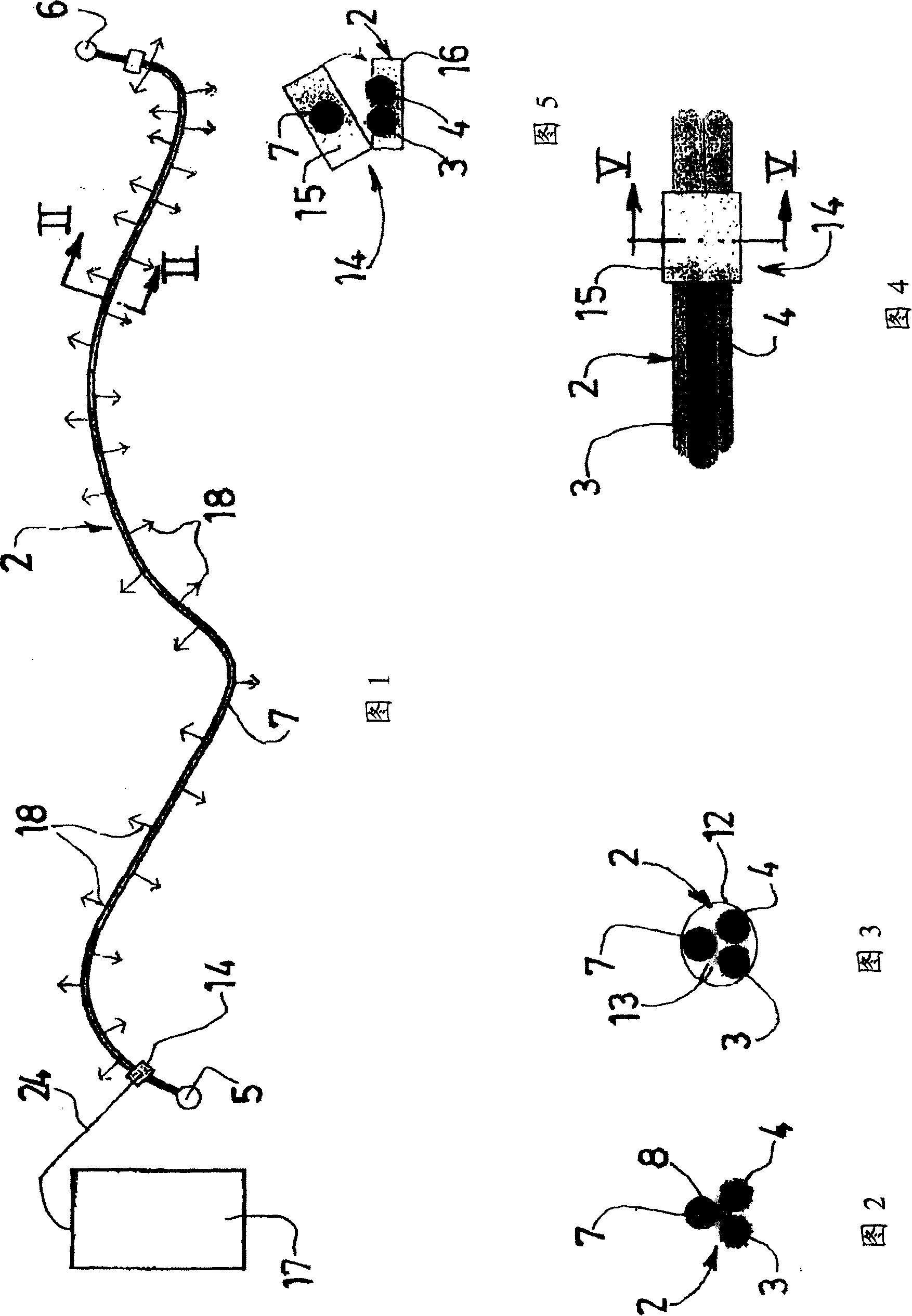
[0041] Referring first to Figures 1 to 5, as an application example, the figure shows a marking device used in combination with a fiber optic jumper, which is a cable generally indicated by reference numeral 2, which contains a combination of Two parallel fibers 3 and 4. The cable 2 has optical connectors 5 and 6 at both ends. Since the optical connector itself is known, it will not be described in detail here.

[0042] The identification device associated with the cable 2 essentially consists of an electroluminescent wire 7 which actually extends along the cable 2 from one end to the other, passing through means which will be described hereinafter. Fasten on cable 2.

[0043] As for the electroluminescent wire 7 , it is a known product per se and hitherto a product that was used especially for decorative purposes. The wire comprises a central electrical conductor or "core" covered by a phosphor-based layer having electroluminescent properties. The layer itself is in turn ...


PUM


Abstract

The identification device comprises at least one electroluminescent wire that extends along the cable or duct to be identified. The electroluminescent wire is designed to be electrically supplied in a temporary manner, so as to display the path of the cable or duct. This device is applicable to the identification of electrical cables, or pneumatic and hydraulic ducts, or fibre-optic cables or cords.

Description

technical field [0001] The present invention relates to a device for visually marking cables or pipes, which can be used in the electrical field, data processing field, etc. in relation to cables, and also in the pneumatic and hydraulic fields in relation to pipes . Here, the term "cable" covers not only wires and cables of any length and any size for transmitting signals or power, but also covers such as those called optical fiber "patch cords" (or "jumper cords") fiber optic cable. Background technique [0002] In the various technical fields mentioned above, the problem that often arises is how to identify and / or trace cables or conduits, either to identify a cable or conduit from a relatively large number of cables or conduits, or to simply determine the The route of the line or pipe. For example, it may be necessary to identify and trace a data processing "jumper wire" located in a splice box interspersed with multiple other similar wires. [0003] Currently, there ...

Claims


Application Information

Patent Timeline
Patent Type & Authority Applications(China)
IPC IPC(8): H02G3/02H02G9/06G02B6/00G08B5/22H05B33/00H01R11/00H01R11/11H01R11/22
CPCG01V15/00H01B7/36
Inventor 帕特里斯·布律内
Owner 帕特里斯·布律内
Learn More