Dehumidifier and control method thereof

A control method and dehumidifier technology, applied in heating and ventilation control systems, heating methods, lighting and heating equipment, etc., can solve the problems of low indoor air dehumidification capacity and long time, so as to prevent the entry of foreign objects and improve the convenience of use sexual effect

Inactive Publication Date: 2008-05-14
LG ELECTRONICS (TIANJIN) APPLIANCES CO LTD
View PDF0 Cites 5 Cited by
  • Summary
  • Abstract
  • Description
  • Claims
  • Application Information

AI Technical Summary

Problems solved by technology

[0007] However, the above-mentioned existing dehumidifiers have the following disadvantages: indoor air is sucked in from the rear of the dehumidifier to the front, and after dehumidification, the dehumidified air is only discharged from the front of the dehumidifier. It takes quite a long time to dehumidify the indoor air above the dehumidifier

Method used


Image

  • Dehumidifier and control method thereof
  • Dehumidifier and control method thereof
  • Dehumidifier and control method thereof

Examples


Embodiment Construction

[0041] Below in conjunction with accompanying drawing and specific embodiment the present invention is described in further detail:

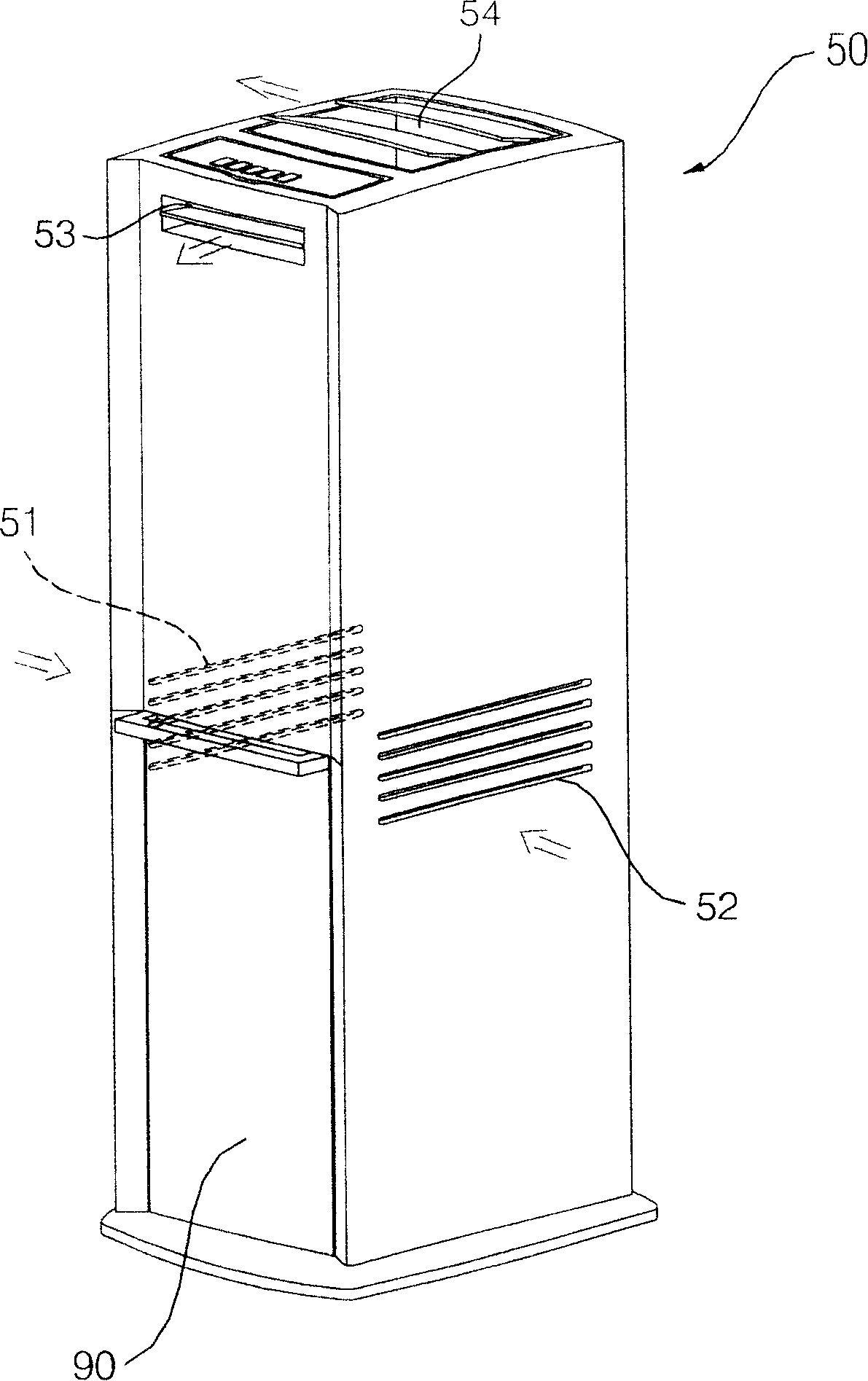
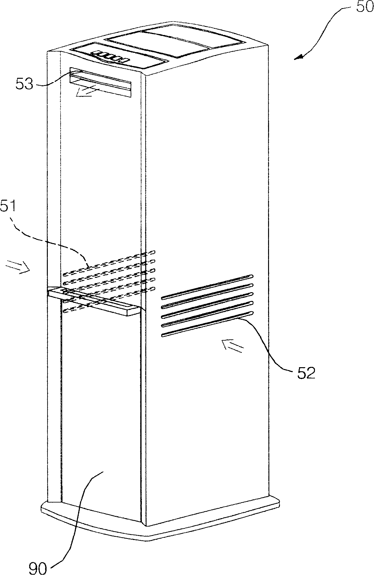
[0042] figure 1 It is a schematic diagram of the three-dimensional structure of the dehumidifier of the present invention in a strong dehumidification state. figure 2 It is a three-dimensional structure schematic diagram of the dehumidifier of the present invention in a weak dehumidification state.

[0043] Such as figure 1 and figure 2 As shown, the dehumidifier of the present invention includes a casing 50 that constitutes the appearance. Air suction ports 51, 52 for sucking indoor air are formed on the left and right sides of the casing 50, and air inlets 51, 52 for discharging dehumidified air are formed. Air outlets 53,54.

[0044] A left air inlet 51 is formed on the left side of the casing 50 , and a right air inlet 52 is formed on the right side.

[0045] A front air outlet 53 is formed on the front of the casing 50 , and a top ...


PUM


Abstract

The invention discloses a dehumidifier, which comprises a shell that is provided with an air absorbing inlet at the side, a front air discharging outlet at the front and a top surface air discharging outlet at the top surface, a wind sending machine that absorbs the air through the air absorbing inlet and then transports the air to the front air discharging outlet and the top surface air discharging outlet, a heat exchanger that consists of an evaporator and a condenser and is used for operating heat exchanging with the air absorbed through the air absorbing inlet, a top surface wind guiding plate that is used for opening / closing the top surface air discharging outlet, and a top surface wind guiding plate motor that is used for driving the top surface wind guiding plate to rotate. The invention has the beneficial effects that the user can choose the discharging of the dehumidified air only from the frontage, or respectively from the frontage and the upward side, thereby having the advantage of conveniently adjusting the indoor dehumidifying state.

Description

technical field [0001] The invention relates to a dehumidifier and its control method. Background technique [0002] Figure 9 It is a schematic diagram of the decomposition structure of the existing dehumidifier; Figure 10 It is a schematic diagram of the internal structure of an existing dehumidifier. [0003] Such as Figure 9 and Figure 10 As shown, the existing dehumidifier includes: forming the appearance of the left and right sides and the top surface, and opening the front and bottom surfaces of the casing 1; arranged inside the casing 1, composed of an evaporator 2 and a condenser 3 with dehumidification Functional heat exchanger 4; the compressor 10 used to compress the refrigerant circulated in the evaporator 2 and condenser 3; the front or rear of the heat exchanger 4 is arranged to provide indoor air into the The air blower fan 5a and the motor 5b of the air blowing power output to the room again after the inside of the casing 1; combined with the front of ...

Claims


Application Information

Patent Timeline
Patent Type & Authority Applications(China)
IPC IPC(8): F24F1/02F24F11/00
Inventor 金纹新
Owner LG ELECTRONICS (TIANJIN) APPLIANCES CO LTD
Why Eureka
Try Eureka