
Target moving object tracking device

A technology for moving objects and tracking equipment, applied in image data processing, instruments, closed-circuit television systems, etc., can solve the problem of unsatisfactory reliable determination of moving objects

Inactive Publication Date: 2008-04-30
MATSUSHITA ELECTRIC WORKS LTD
View PDF1 Cites 39 Cited by
  • Summary
  • Abstract
  • Description
  • Claims
  • Application Information

AI Technical Summary

Problems solved by technology

Therefore, the above scheme is unsatisfactory for achieving reliable determination of moving objects even with the addition of templates

Method used


Image

  • Target moving object tracking device
  • Target moving object tracking device
  • Target moving object tracking device

Examples


Embodiment Construction

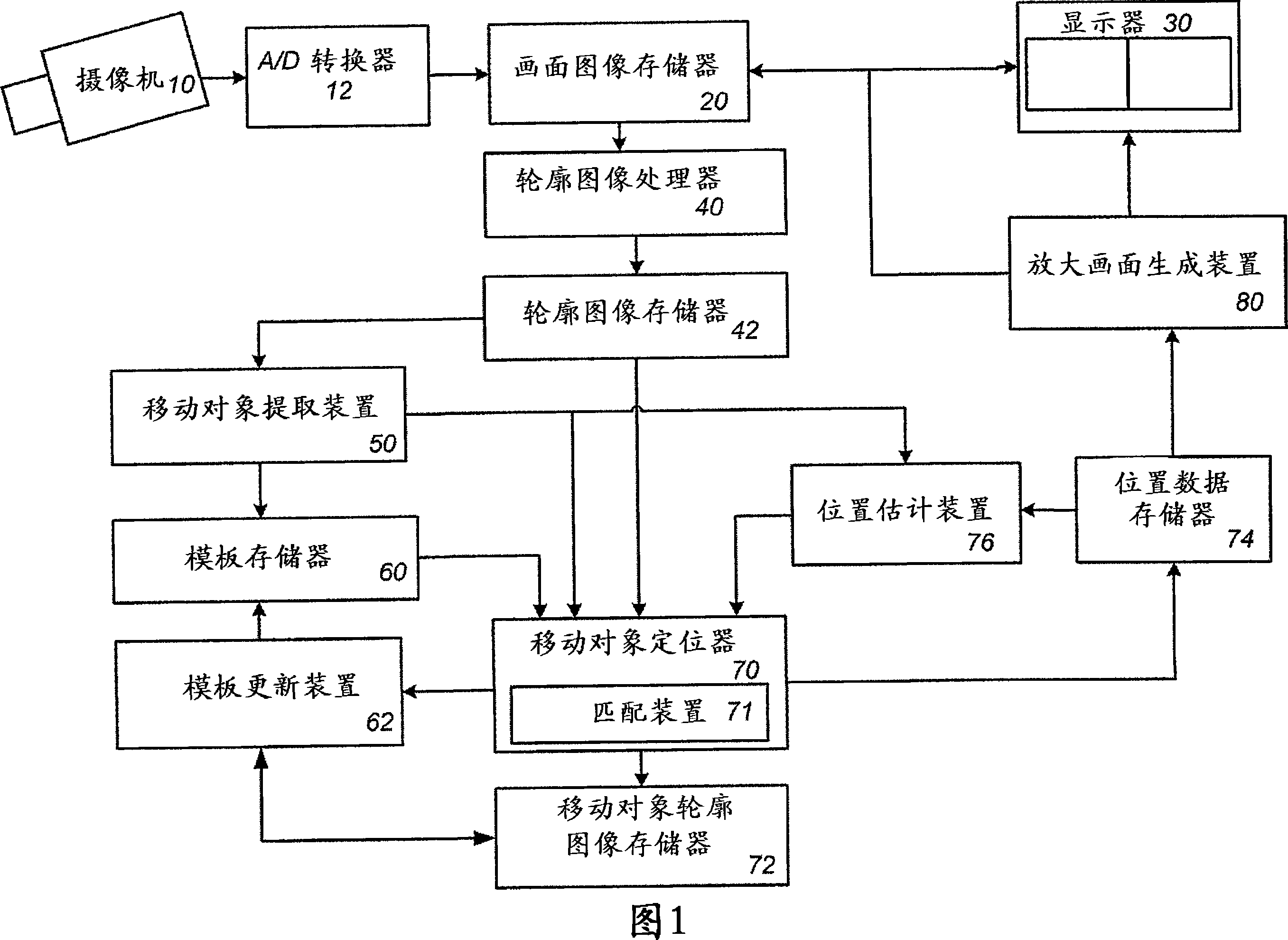
[0046] Referring to FIG. 1, there is shown a target mobile object tracking device according to a preferred embodiment of the present invention. The device is used as an intruder monitoring system to detect an intruder or target moving object, track its movement, and display the intruder in a magnified view for identification of the intruder.

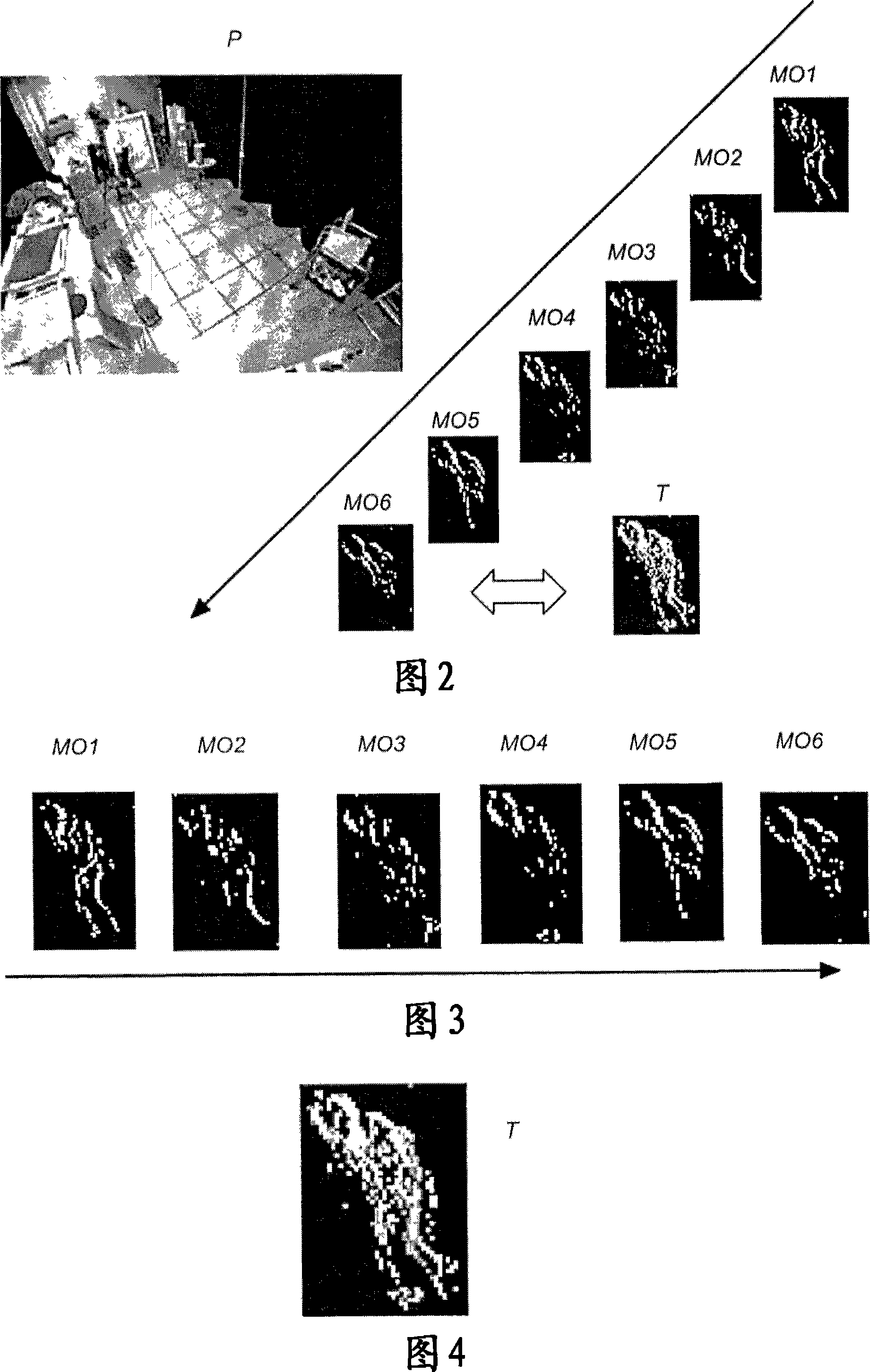
[0047] The device comprises a video camera 10 covering the observation area to take successive pictures which are converted by an A / D converter 12 into time-series digital data of real picture images P covering the entire field of view, as shown in FIG. 2 , and is stored in the screen image memory 20. The device includes a display 30 capable of displaying a current screen image and a magnified view of a selected portion of the current image for identifying a target moving object as will be discussed later. Included in the apparatus is a contour image processor 40 for generating contour images from each of the real picture images in memo...


PUM


Abstract

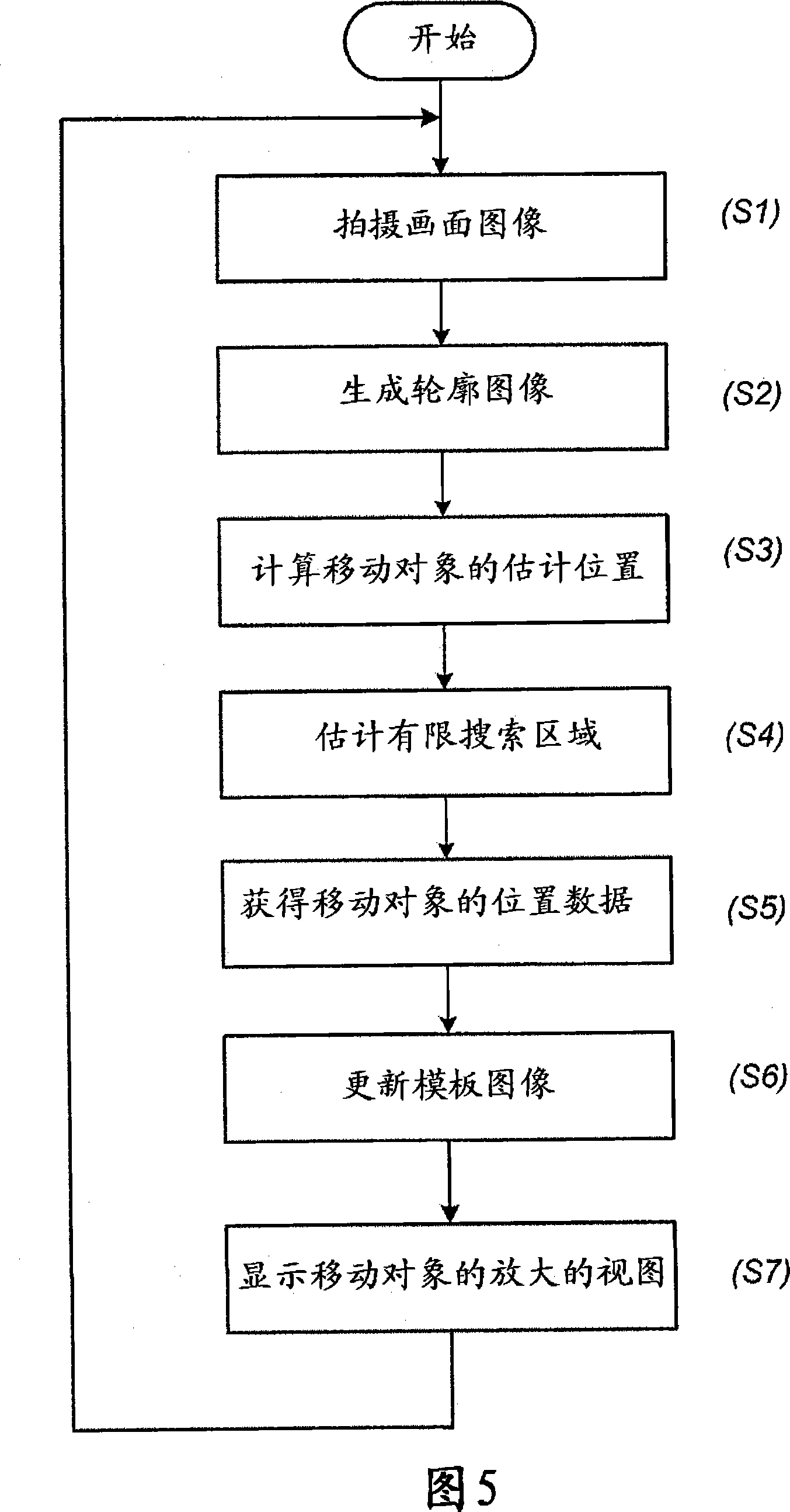
A target moving object tracking device takes a time series of picture images of a target moving object, and track a movement of the moving object in the picture images for displaying an enlarged view of the moving object. The device includes a template memory storing a template image which is compared with each one of time-series outline images given from the picture images to determine a partial area in match with the template image for each of the outline images and extract the partial areas as a moving object outline image. The template image is constantly updated by being replaced with a combination of the previous moving object outline images to accurately reflect the moving object.

Description

technical field [0001] The present invention relates to a target moving object tracking device, and more particularly to such a device for tracking a possible intruder using a video camera. Background technique [0002] There is an increasing need to track and recognize the movement of people by means of cameras in restricted areas around doors or the like. To this end, prior art tracking devices are generally configured to monitor the evolution of images through time series, determine moving object regions within each monitored image, and zoom in on the thus determined moving object regions. However, the moving object area thus determined becomes smaller as the moving object moves faster, which results in poor resolution of the enlarged image of the moving object area. In order to solve this problem, in the paper "Human Tracking Using TemporalAveraging Silhouette with an Active Camera" (Transactions of the Institute of Electronics, Information and Communication Engineers I...

Claims


Application Information

Patent Timeline
IPC IPC(8): H04N7/18G06T7/20
Inventor 古川聪
Owner MATSUSHITA ELECTRIC WORKS LTD
Learn More