A system and method for dynamically correcting parallax in head borne video systems

A dynamic, parallax technology that is used in components of television systems, closed-circuit television systems, stereoscopic systems, etc.

Inactive Publication Date: 2008-04-16
EXCELIS INC
View PDF0 Cites 30 Cited by
  • Summary
  • Abstract
  • Description
  • Claims
  • Application Information

AI Technical Summary

Problems solved by technology

When the parallax of an object at a distance is eliminated by aiming the video system, but the user attempts to locate another object at a close distance, for example, the tool 12 shown in FIG. 1 within the arm's reach of the user , this problem is particularly evident

Method used


Image

  • A system and method for dynamically correcting parallax in head borne video systems
  • A system and method for dynamically correcting parallax in head borne video systems
  • A system and method for dynamically correcting parallax in head borne video systems

Examples


Embodiment Construction

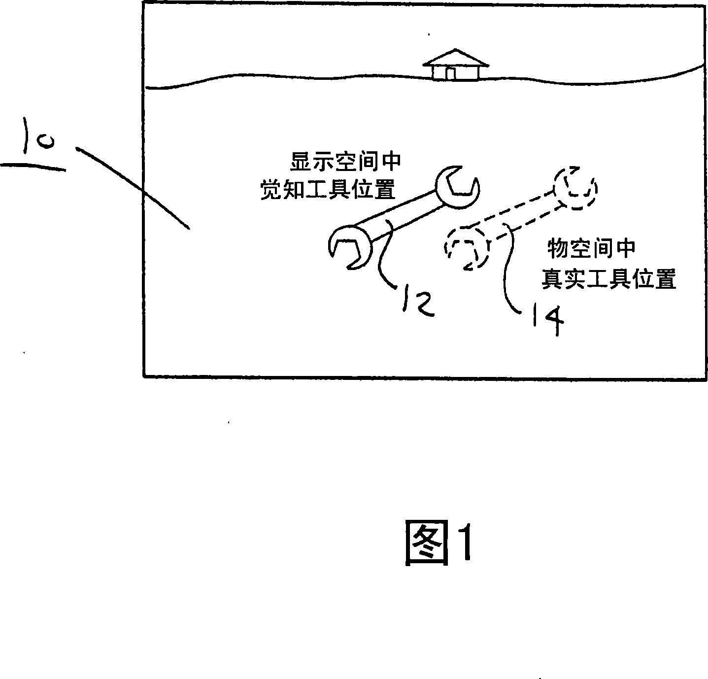
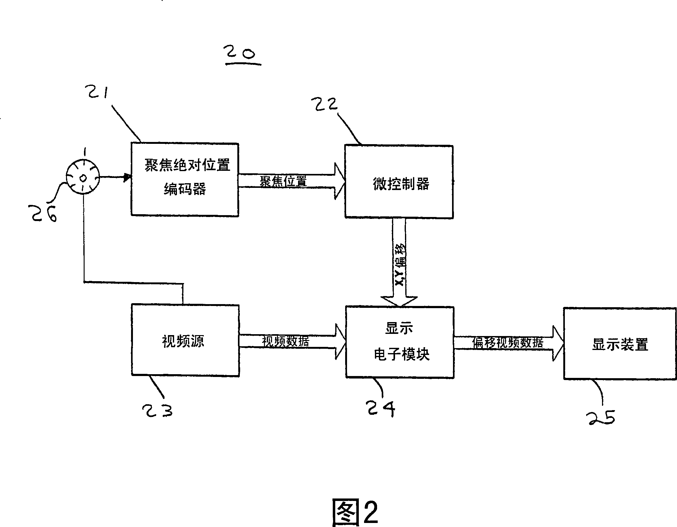
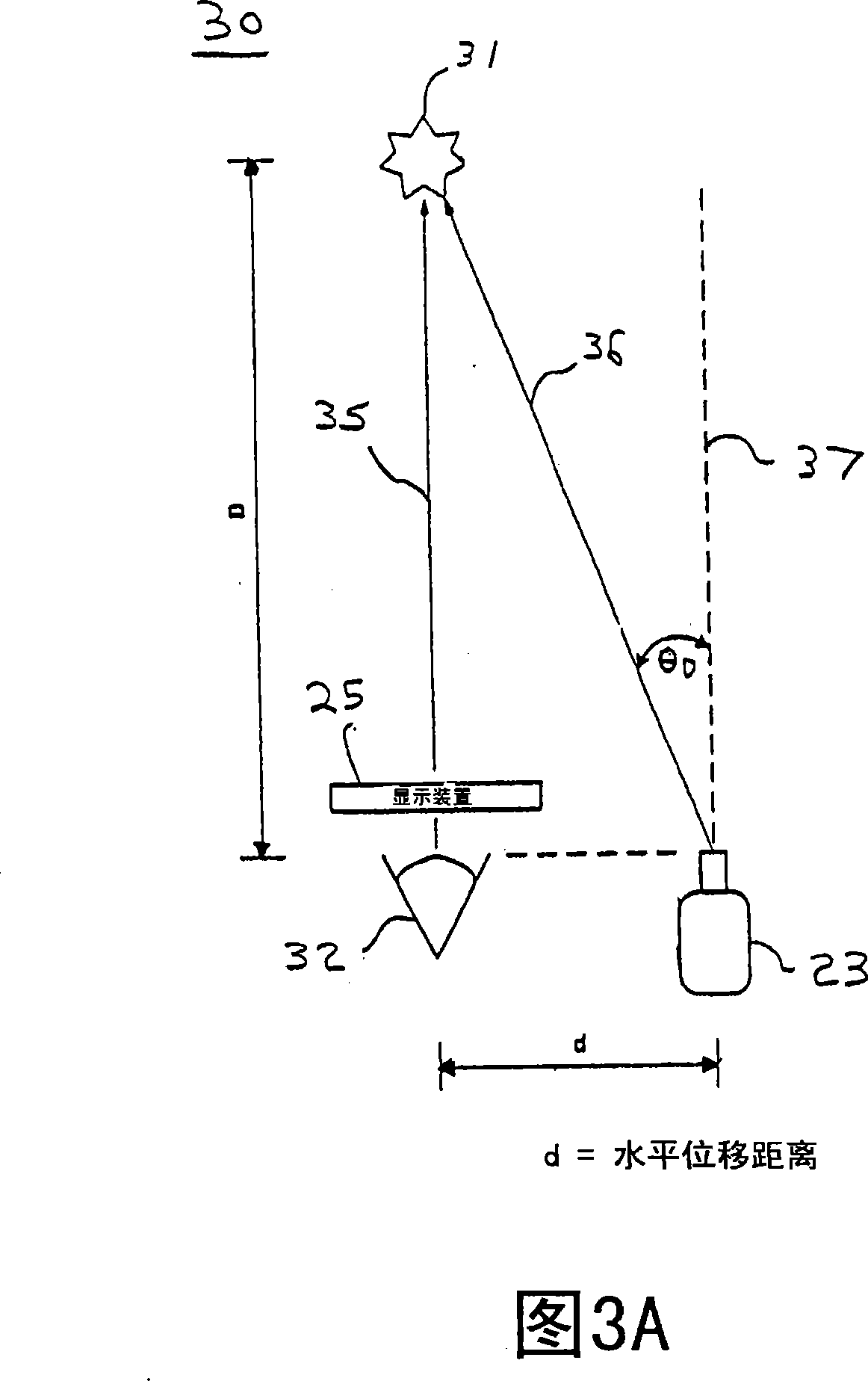
[0032] As described below, the present invention will dynamically realign the video image so that the image matches the real world at all distances. To achieve this, the present invention determines the distance to the object of interest so that dynamic alignment is performed based on the determined distance. In one embodiment, the present invention uses the absolute position of the camera's focus mechanism (or the angular orientation of the manual focus knob) to determine the distance to an object of interest to the user before applying the appropriate amount of parallax correction to the image displayed on the user's display. In this way, the apparent position of the object of interest is correctly perceived as being at its actual position within object space.

[0033] In one embodiment of the invention, the video is provided to the user on a digital display device such as an LCD or LED display. These displays consist of arrays of pixel rows and pixel columns. By controlli...


PUM


Abstract

A dynamically corrected parallax system includes a head borne video source for imaging an object and providing video data. A controller electronically offsets the video data provided from the head borne video source to form offset video data. A display device receives the offset video data and displays the offset video data to a user's eye. The display device is configured for placement directly in front of the user's eye as a vision aid, and the head borne video source is configured for displacement to a side of the user's eye. The offset video data corrects parallax due to horizontal and / orvertical displacement between the display device and the head borne video source. The display device includes an X,Y array of respective columns and rows of pixels, and the offset video data includesan offset of a number of columns of pixels in the X direction of the X,Y array, and / or another offset of a number of rows of pixels in the Y direction of the X,Y array.

Description

technical field [0001] The present invention generally relates to systems for parallax correction. More specifically, the present invention relates to systems and methods for dynamically correcting for parallax in head-mounted displays (HMDs) placed directly in front of a user's eyes. Background technique [0002] Head-worn visual aids are usually positioned directly in front of the eye receiving the aid. As these systems migrated from direct viewing optical paths to digital camera assistance, their system configurations required placing the head-mounted display (HMD) directly in front of the user's assisted eye with an eye gap of one inch. This placement of the HMD precludes simultaneously placing the camera aperture directly in front of the eye receiving the assistance. The camera iris must be moved to the front of the HMD or to the side of the HMD. [0003] For example, if a digital camera is placed 100mm from the optical axis of the assisted eye, a displacement will b...

Claims


Application Information

Patent Timeline
Patent Type & Authority Applications(China)
IPC IPC(8): H04N7/18H04N13/00G06T15/10G02B27/02G06T3/00G09G3/20G09G5/00G09G5/36G09G5/38H04N5/64
CPCH04W40/248G02B2027/0138H04W8/005G02B27/017G02B2027/014G02B2027/0129H04W84/18
Inventor T·K·特鲁多B·R·多比
Owner EXCELIS INC
Why Eureka
Try Eureka