Method and apparatus for mounting a rotating reflector antenna to minimize swept arc

A reflector antenna, reflector technology, which is applied to antennas, antennas, electrical components and other directions suitable for movable objects, can solve problems such as increasing aircraft resistance and increasing the front surface area of ​​radomes

Active Publication Date: 2008-04-09
THE BOEING CO
View PDF0 Cites 2 Cited by
  • Summary
  • Abstract
  • Description
  • Claims
  • Application Information

AI Technical Summary

Problems solved by technology

this necessitates a radome of considerable width, thereby increasing the frontal surface area of ​​the radome and thus increasing the drag of the aircraft

Method used


Image

  • Method and apparatus for mounting a rotating reflector antenna to minimize swept arc
  • Method and apparatus for mounting a rotating reflector antenna to minimize swept arc
  • Method and apparatus for mounting a rotating reflector antenna to minimize swept arc

Examples


Embodiment Construction

[0020] The following description of a preferred embodiment is by way of example only and is not intended to pose any limitation on the system, its application or use.

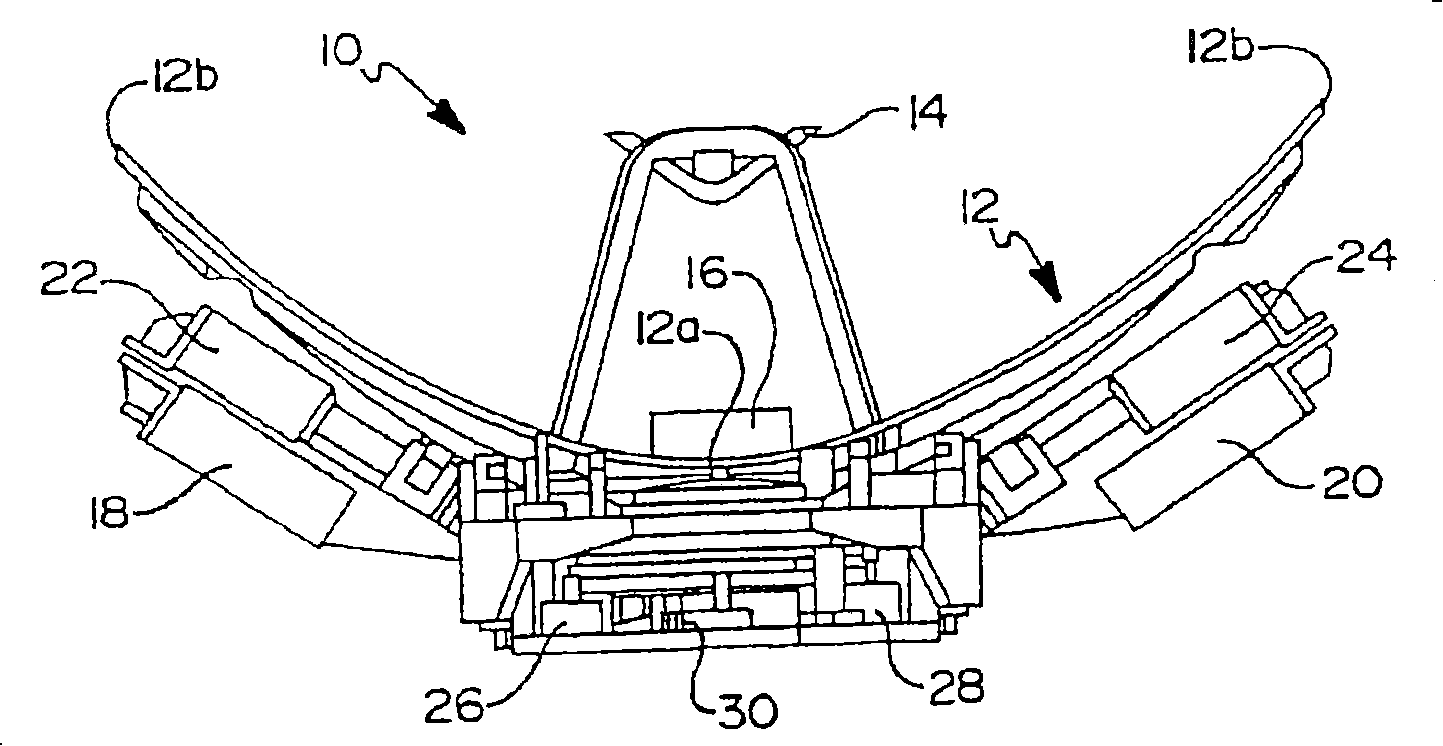
[0021] refer to figure 2 , which shows a prior art antenna system 10 that is well suited for mounting on the exterior surface of an aircraft. Antenna system 10 includes a main reflector 12 having a center (ie, apex) 12a and an outermost portion 12b. The auxiliary reflector 14 is located in front of the feed horn 16 at the center 12a of the main reflector 12 . A pair of low noise amplifiers (LNA) 18 and 20, and a pair of diplexers 22 and 24 are used to perform signal conditioning operations on the received and transmitted signals. An elevation motor 26 is used to position the main reflector 12 at a desired elevation angle, while an azimuth motor 28 is used to rotate the main reflector 12 about an azimuth axis to position the main reflector at a desired azimuth. Encoder 30 is used to track the orientation of m...


PUM


Abstract

An apparatus and method for mounting a rotatable reflector antenna system on an outer surface of an aircraft which minimizes a swept arc of a main reflector. This allows the effective frontal area of the main reflector to be reduced such that a radome with a smaller frontal area can be employed to cover the antenna system. The main reflector is rotated about an azimuth axis which is disposed forward of an axial center (i.e., vertex) of the main reflector. In one embodiment the azimuth axis is located in a plane extending between the outermost lateral edges of the main reflector, which define the aperture of the antenna. In another embodiment the azimuth axis is located forward of the outermost lateral edges of the main reflector. In further embodiments the azimuth axis of rotation is located in between a subreflector and a feed horn of the antenna, or in between the vertex of the main reflector and the subreflector.

Description

[0001] This application is a continuation-in-part of co-pending US Patent Application No. 09 / 965,688 filed September 27,2001. The disclosure of the aforementioned application is hereby incorporated by reference. technical field [0002] The present invention relates to antenna systems, and more particularly to a method and apparatus for mounting a reflector antenna in a manner that minimizes the arc sweep of the antenna as the antenna rotates about its azimuth axis. Background technique [0003] The front surface area of ​​an antenna mounted under a radome on an aircraft is very important to the aerodynamics of the aircraft. This is due to the air resistance created by the radome and the effect it has on aircraft performance and fuel consumption. For a reflector antenna that must rotate about its azimuth axis, the antenna's "sweep arc" is larger than the overall width of the antenna's main reflector. This necessitates a radome of considerable width, thereby increasing the ...

Claims


Application Information

Patent Timeline
Patent Type & Authority Applications(China)
IPC IPC(8): H01Q3/04H01Q19/19H01Q1/28
CPCH01Q3/04H01Q1/28H01Q19/19
Inventor 格伦·J·德萨甘特艾伯特·L·比恩
Owner THE BOEING CO
Why Eureka
Try Eureka