Yarn processing system and controlled yarn tension device

A yarn brake, processing system technology, applied in the direction of transportation and packaging, textile and paper, thin material handling, etc., to achieve the effect of compact form

Active Publication Date: 2012-08-29
VANDEWIELE SWEDEN AB
View PDF7 Cites 0 Cited by
  • Summary
  • Abstract
  • Description
  • Claims
  • Application Information

AI Technical Summary

Problems solved by technology

A big disadvantage is that when the thread is interrupted between the yarn feeding device and the controllable yarn brake or at the controllable yarn brake, the error detection signal of the weft thread detector will be delayed until the freedom of the thread breakage. It takes a certain amount of time for the end of the thread to pass through the output hole

Method used


Image

  • Yarn processing system and controlled yarn tension device
  • Yarn processing system and controlled yarn tension device
  • Yarn processing system and controlled yarn tension device

Examples


Embodiment Construction

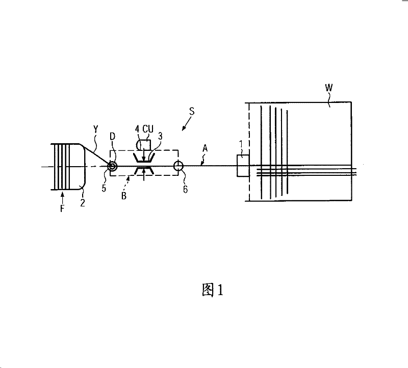
[0022] figure 1 A yarn processing system S is shown, comprising a loom W with at least one yarn channel A, in which a yarn feeding device F and a controllable yarn brake B are arranged, which are mounted on The yarn feeding device F leads downstream of the yarn path of the yarn feeding system 1 of the loom W. In addition, a piezoelectric weft detector D is set in the yarn path, and its function is to generate an error detection signal when the yarn feeding system 1 is interrupted or wireless, so that the yarn processing system suspends work, thereby avoiding or reducing Yarn defect. The general operating principle of the weft yarn detector D is that the error detection signal is generated by the difference between the yarn movement and the yarn stop, and the yarn must be in a moving state when the error detection signal occurs.

[0023] The loom W may be a projectile loom or a rapier loom. The yarn feeding device F is a yarn feeding device with a top unwinding device of the...


PUM


Abstract

The invention relates to a yarn processing system (S) with a weaving machine (W) comprising at least one yarn channel (A) inside of which a yarn feeder (F) with an unwinding over head is provided as well as a controlled yarn tension device (B), which is located downstream from the yarn feeder and which has a piezoelectric weft yarn detector mounted thereon. The yarn tension device (B) comprises the entry and exit eyelet (5, 6) that defines the essentially linear tensioned yarn path. The weft yarn detector (D) is integrated in the entry eyelet (5). In the controlled yarn tension device (B), the piezoelectric weft yarn detector (D) is provided next to or inside the entry eyelet (5).

Description

technical field [0001] The invention relates to a yarn processing system according to the preamble of claim 1 and to a controllable yarn brake according to the preamble of claim 10 . Background technique [0002] In the yarn processing system disclosed in EP1061166A, a piezoelectric weft yarn detector is mounted in an output hole fitted on the housing of a controllable yarn brake. The input and output openings of the controllable yarn brake define a substantially linear yarn braking path, for example between brake discs or between a brake disc and a fixed friction surface. In order for the piezoelectric weft thread detector in the output hole to obtain sufficient yarn contact pressure away from the controllable yarn brake, it must be determined that this yarn reversal must be compensated for significantly different types of yarn material , even if only small yarn reversals at the delivery hole need to be adjusted. A big disadvantage is that when the thread is interrupted b...

Claims


Application Information

Patent Timeline
Patent Type & Authority Patents(China)
IPC IPC(8): B65H51/22B65H59/24D03D47/34
CPCB65H59/24B65H2701/31D03D47/34D03D51/34
Inventor 佩尔·约瑟夫松
Owner VANDEWIELE SWEDEN AB
Why Eureka
Try Eureka