Lifting-type storage device
A storage device, a lift-type technology, applied in the field of lift-type storage devices
- Summary
- Abstract
- Description
- Claims
- Application Information
AI Technical Summary
Problems solved by technology
Method used
Image
Examples
no. 1 Embodiment approach
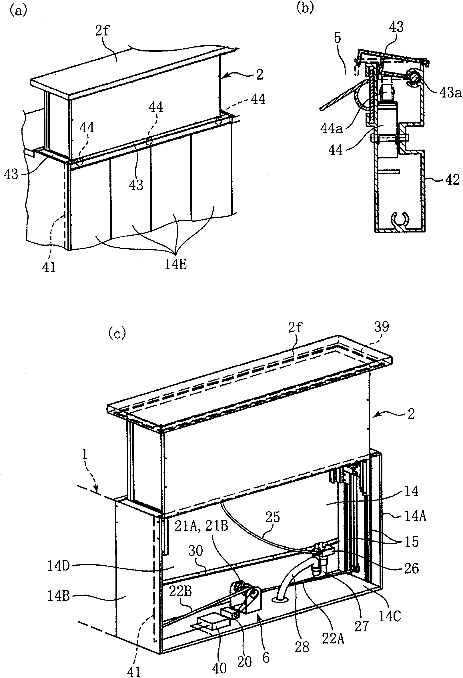
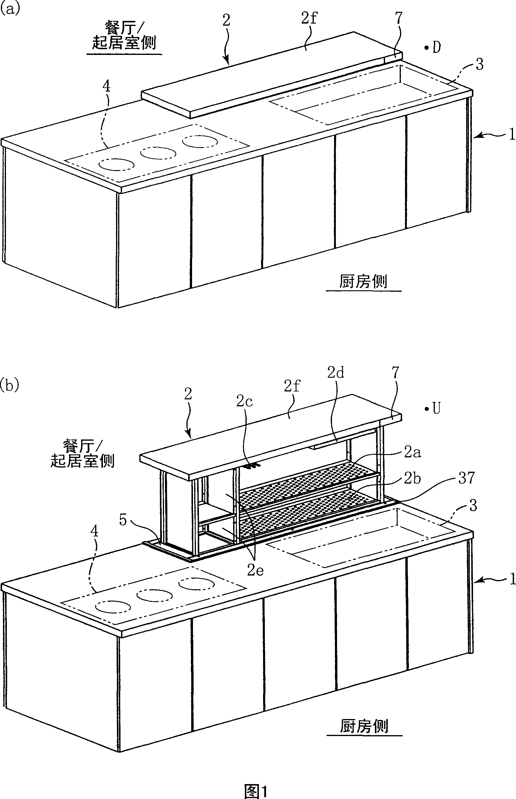
[0036] figure 1 It is the kitchen base cabinet 1 which concerns on one Embodiment of this invention. (a) is a perspective view of the draining rack (storage rack) 2 in the lowered position (when not in use) D, and (b) is a perspective view of the draining rack 2 in the raised position (in use) U. figure 1 The base cabinet 1 exemplifies an open face-to-face kitchen without a wall between the kitchen and the dining room, however, the present invention can also be implemented in kitchens other than the open face-to-face kitchen.
[0037] A sink 3 is arranged on the right side of the counter of the above-mentioned base cabinet 1 , and a storage rack, that is, a draining rack 2 , is arranged at the rear position of the sink 3 . In addition, the drain rack 2 can also be arranged at the side of the water tank 3 . A stove 4 is arranged on the left side of the counter of the above-mentioned base cabinet 1 . Here, the expression of the left-right or front-back direction refers to t...
no. 2 Embodiment approach
[0085] Figure 12 It is a block diagram showing the circuit structure of the sensing part related to the lifting and lowering of the drain rack 2 in the control box 40' of the kitchen base cabinet in another embodiment of the present invention. The structure of the kitchen base cabinet in this embodiment can adopt the structure of the above-mentioned kitchen base cabinet 1 , and it should be noted that the methods for determining foreign objects are different. This control box 40' replaces the aforementioned control box 40, and can realize the following functions.
[0086] In the base cabinet of this embodiment, as the sensor related to the lifting of the draining rack 2, in addition to the above-mentioned static detection sensor 38 and piezoelectric sensor 39, a sliding resistor 45 and a photointerrupter for detecting the lifting position of the draining rack 2 are also provided. 46 (Photo Interrupter). An arithmetic processing circuit 50 composed of a microcomputer or the ...
no. 3 Embodiment approach
[0103] Figure 14 It is a figure which shows the change of the determination threshold value of the kitchen base cabinet which concerns on another embodiment of this invention. In the kitchen floor cabinet of the present embodiment, the above-mentioned Figure 12 Only a part of the structure and operation of the correction unit 50d and the storage unit 50c of the calculation processing circuit 50 are different. Figure 14 A diagram with the above Figure 13 The graphs shown correspond to . It should be noted that, in this embodiment, the storage unit 50c stores the default value of the change mode shown by the reference symbol α1, and as shown by the reference symbol α1", the lifting range of the drain rack 2 is divided into a plurality of intervals, The determination threshold indicated by the above-mentioned reference symbol α1' is stored as a maximum value or an average value of each section.
[0104] When at the stop position, the correction unit 50d modifies the judgm...
PUM
 Abstract
Description
Claims
Application Information
 - R&D
- Intellectual Property
- Life Sciences
- Materials
- Tech Scout
- Unparalleled Data Quality
- Higher Quality Content
- 60% Fewer Hallucinations
Browse by: Latest US Patents, China's latest patents, Technical Efficacy Thesaurus, Application Domain, Technology Topic, Popular Technical Reports.
© 2025 PatSnap. All rights reserved.Legal|Privacy policy|Modern Slavery Act Transparency Statement|Sitemap|About US| Contact US: help@patsnap.com


