
Free space optical communication system between multiple mobile platforms

A technology of optical communication system and mobile platform, which is applied in the direction of free space transmission, transmission system, electromagnetic wave transmission system, etc., and can solve problems such as inappropriate systems and methods

Inactive Publication Date: 2011-11-09
ZHEJIANG UNIV +1
View PDF1 Cites 2 Cited by
  • Summary
  • Abstract
  • Description
  • Claims
  • Application Information

AI Technical Summary

Problems solved by technology

For free-space optical communication between multiple mobile platforms, the key point is to realize multipoint-to-multipoint communication. The above-mentioned systems and methods are not suitable solutions.

Method used


Image

  • Free space optical communication system between multiple mobile platforms
  • Free space optical communication system between multiple mobile platforms
  • Free space optical communication system between multiple mobile platforms

Examples


Embodiment Construction

[0066] The specific implementation manner of the free-space optical communication system among multiple mobile platforms of the present invention will be described in detail below with reference to the accompanying drawings.

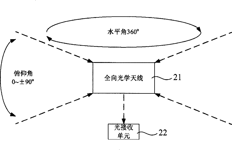
[0067] The invention provides an omnidirectional transmitter and an omnidirectional receiver, which are combined with traditional directional transmitters and directional receivers to realize free-space optical communication between multiple mobile platforms.

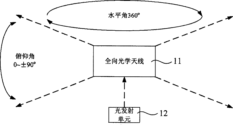
[0068] see figure 1 , figure 1 It is a structural schematic diagram of the omnidirectional transmitter of the present invention.

[0069] As shown in the figure, in the omnidirectional transmitter of the present invention, the light emitting unit 12 emits laser light at a horizontal angle of 360° in the horizontal direction through the omnidirectional optical antenna 11, and the laser emission pitch angle in the vertical direction can be according to The communication distance of the system, the...


PUM


Abstract

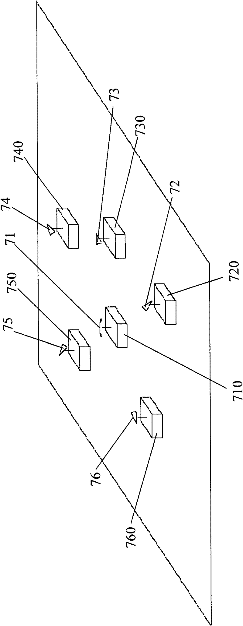
This invention relates to a free space optical communication system among multiple mobile platforms, which sets at least one primary mobile station in a working region installed with a full-way transceiver of a full-way optical antenna or a full-way emitter and a full-way receiver and sets several slave mobile platforms installed with a directional transceiver or a directional emitter and a directional receiver to realize full-way emission and reception to the slave mobile platforms from the primary platform and directional emission and reception to the primary platform from the slave platforms, and the full-way transceiver means an emitter and a receiver share a full-way optical antenna, which realizes free space optical communication among multiple mobile platforms with traditional directional emitters and receivers.

Description

technical field [0001] The invention relates to the communication technology among multiple mobile platforms in the category of free space optical communication. Background technique [0002] In the existing free space optical communication system, there are two application modes, one is applied to fixed platforms, such as between buildings, laser communication is realized by laser directional emission and laser directional reception, transmitter and receiver The machine needs manual alignment in advance. The Chinese patent 99815992.1 of LSA Company discloses such a laser communication system and method for directional emission and directional reception. The other is applied to mobile platforms, such as satellite-to-satellite or ground-to-satellite, which also uses laser directional emission and laser directional reception to achieve laser communication, but there are special aiming and tracking devices between the two communication platforms to achieve alignment. [0003]...

Claims


Application Information

Patent Timeline
Patent Type & Authority Patents(China)
IPC IPC(8): H04B10/00H04B10/112
Inventor 李捷聂亮项震葛剑虹刘崇
Owner ZHEJIANG UNIV
Learn More