
Vibrating conveyor

A technology of vibrating conveyors and transmission devices, applied in the field of conveyors, can solve the problems of amplitude variation, inconstant amplitude and excitation force, and unstable conveying speed, and achieve the effects of constant amplitude, stable conveying speed and direction.

Inactive Publication Date: 2008-02-20
江苏保龙机电制造有限公司
View PDF0 Cites 14 Cited by
  • Summary
  • Abstract
  • Description
  • Claims
  • Application Information

AI Technical Summary

Problems solved by technology

The main defects of the vibrating conveyor adopting the current eccentric transmission structure type are: the amplitude is changing, and the eccentricity cannot be fixed, which makes the amplitude and exciting force of the vibrating conveyor unstable during the working process, and the feeding speed is unstable. Highly affected by materials

Method used


Image

  • Vibrating conveyor
  • Vibrating conveyor
  • Vibrating conveyor

Examples


Embodiment Construction

[0019] The present invention will be described in further detail below in conjunction with the accompanying drawings and embodiments.

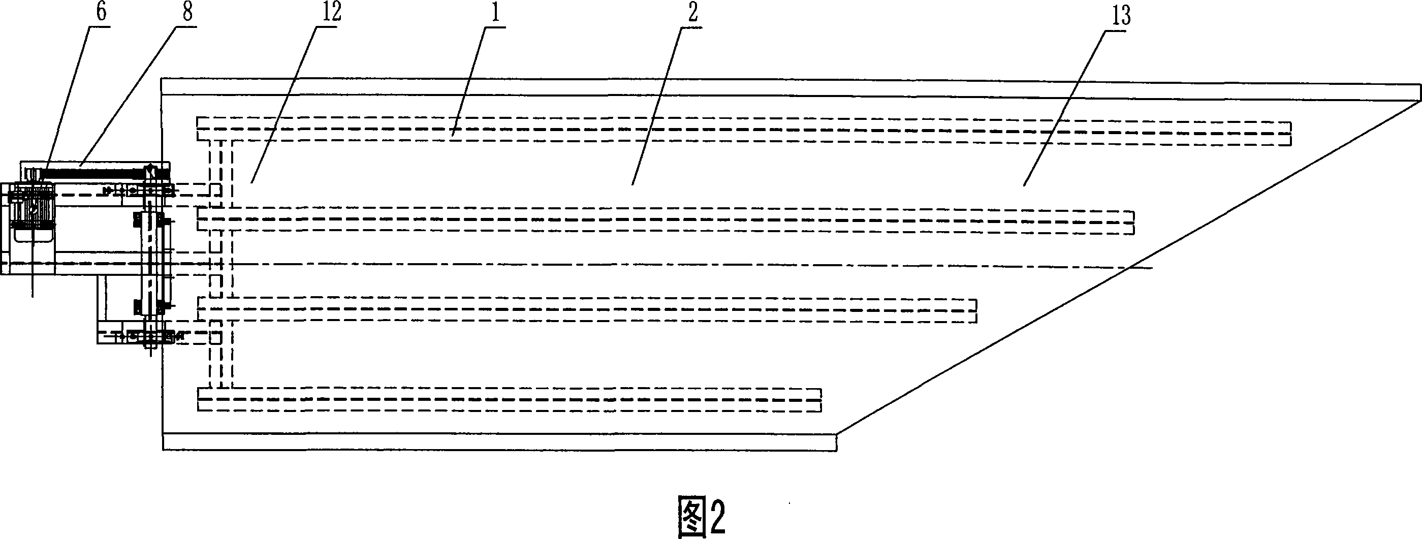
[0020] As shown in FIGS. 1 to 6 , a vibrating conveyor includes a base 1 , a tank body 2 , a transmission device 3 , a swing arm 5 , a spring 7 , and also includes a hinge 4 and a pin 9 . The tank body 2 is open, and one end of the tank body 2 is a feed end 12 , and the other end is a discharge end 13 . Transmission device 3 comprises motor 6, small pulley 29, large pulley 23, belt 28, eccentric shaft 16, outer bearing seat 22, inner bearing seat 17, inner bearing cover 18, bearing 21, rectangular steel 19, and motor 6 is arranged on the groove On one side of the feeding end 12 of the body 2, the motor 6 is fixed on the base 1 by bolts, the motor 6 is fixedly connected with the small pulley 29, the small pulley 29 is connected with the large pulley 23 through the belt 28, the large pulley 23, the small pulley 29 1. Belt 28 outer cover has bel...


PUM


Abstract

The invention relates to a conveyor, in particular to a vibration conveyor and consists of a pedestal(1), a groove body(2), a transmission device(3), a swing arm(5) and a spring(7). One end of the groove body (2) is the feed end(12) and the other end is the discharge end(13), the transmission device(3) and the groove body(2) are fixedly connected, the groove body(2) is movably connected with the pedestal(1) through the swing arm(5) and a spring(7), the transmission device(3) consists of a motor(6), a small belt wheel(29), a large belt wheel(23), a belt(28), an eccentric shaft(16), an outer bearing base(22), an inner bearing base(17) and a bearing(21). The eccentric shaft(16) is fixedly connected with the large belt wheel(23). The eccentric shaft(16) is movably connected with the inner bearing base(17) and the outer bearing base(22) through the bearing(21). The invention has the advantages that the motor drives the eccentric shaft as the power source, the vibration frequency is constant and the feed speed and the direction are stable.

Description

technical field [0001] The invention relates to a conveyor, in particular to a vibrating conveyor. Background technique [0002] Drum chipper is a main equipment used in wood-based panel, pulp and paper and other industrial material preparation and chipping sections, and the vibrating conveyor is a kind of conveying equipment in the feeding and conveying system of drum chipper. It has The role of dispersing the piles of logs allows the logs to enter the chipper evenly and smoothly, which is used to solve the bridging, blocking, uneven feeding and poor conveying equipment of the chipper in the feeding of logs. The existing vibrating conveyor generally includes a base, a tank body, a transmission device, a swing arm, and a spring. The tank body is open, and the tank body is connected to the base through a swing arm and a spring. The trough is driven by eccentric transmission. There are two main types of transmission devices: one uses eccentric vibrator to complete eccentric t...

Claims


Application Information

Patent Timeline
Patent Type & Authority Applications(China)
IPC IPC(8): B65G27/04B65G27/18
Inventor 周水保圣爱兵赵志方
Owner 江苏保龙机电制造有限公司
Learn More