Movement sensing device

A motion perception, motion sensor technology, applied in the direction of instrument, electrical digital data processing, data processing input/output process, etc. Competence and other issues, to achieve the effect of improved convenience, obvious progress, and simplified structure

Inactive Publication Date: 2008-02-13
APEXONE MICROELECTRONICS
View PDF1 Cites 14 Cited by
  • Summary
  • Abstract
  • Description
  • Claims
  • Application Information

AI Technical Summary

Problems solved by technology

[0006] However, with the continuous development of science and technology, the limitations of the traditional mouse will become more and more obvious due to its own structure.
In particular, when the mouse or similar optical motion sensing device is applied in a portable mobile device, its disadvantage of being inconvenient to operate is fully revealed.
For example, when the mouse needs to move on uneven surfaces such as clothing and skin, the accuracy and reliability of the user's operation will be affected due to the wide bottom surface and large shape of the mouse.
Furthermore, portable mobile devices are getting smaller and smaller, and when an optical motion sensing device is needed for input operations, the traditional mouse is even more incompetent.

Method used


Image

  • Movement sensing device
  • Movement sensing device
  • Movement sensing device

Examples


Embodiment Construction

[0025] Various embodiments of the present invention will be described in detail below with reference to the accompanying drawings, in which the same structures or functions are marked with the same numerals. It should be pointed out that the purpose of the drawings is only to facilitate the description of the specific embodiments of the present invention, and is not a redundant description or limitation to the scope of the present invention. In addition, the drawings are not necessarily drawn to scale.

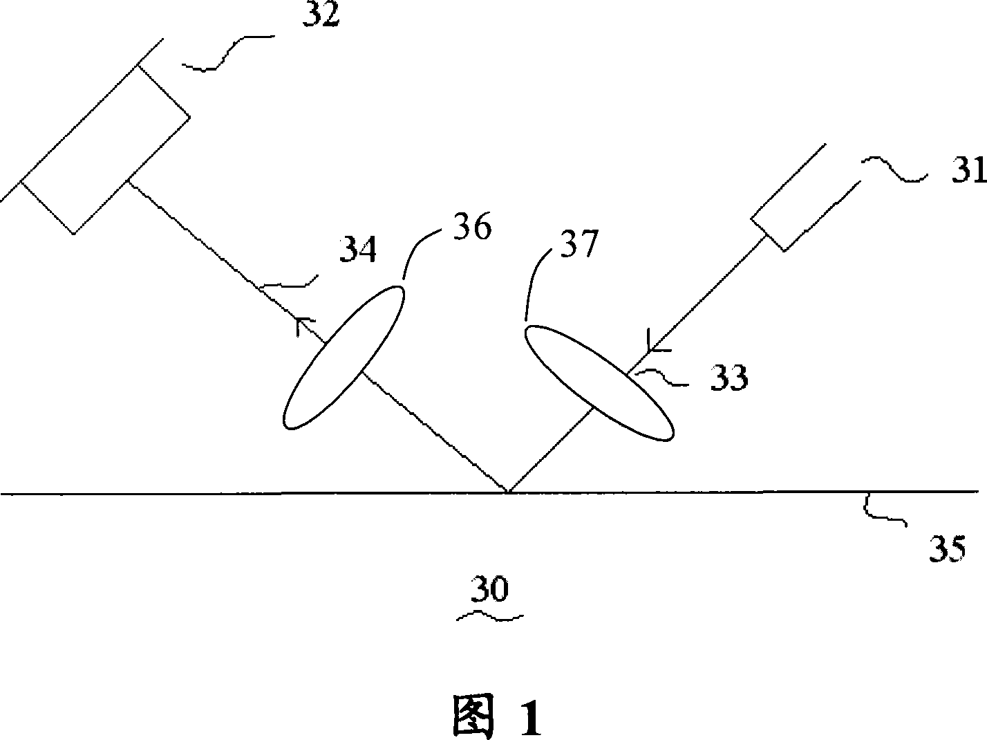
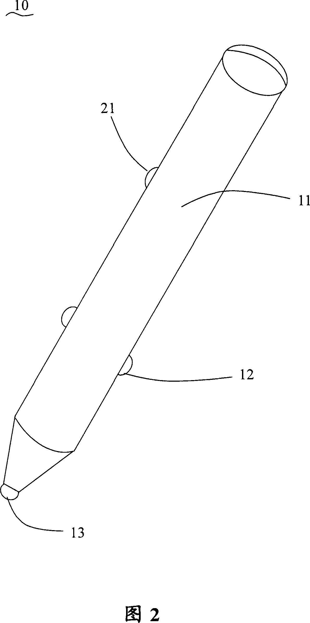
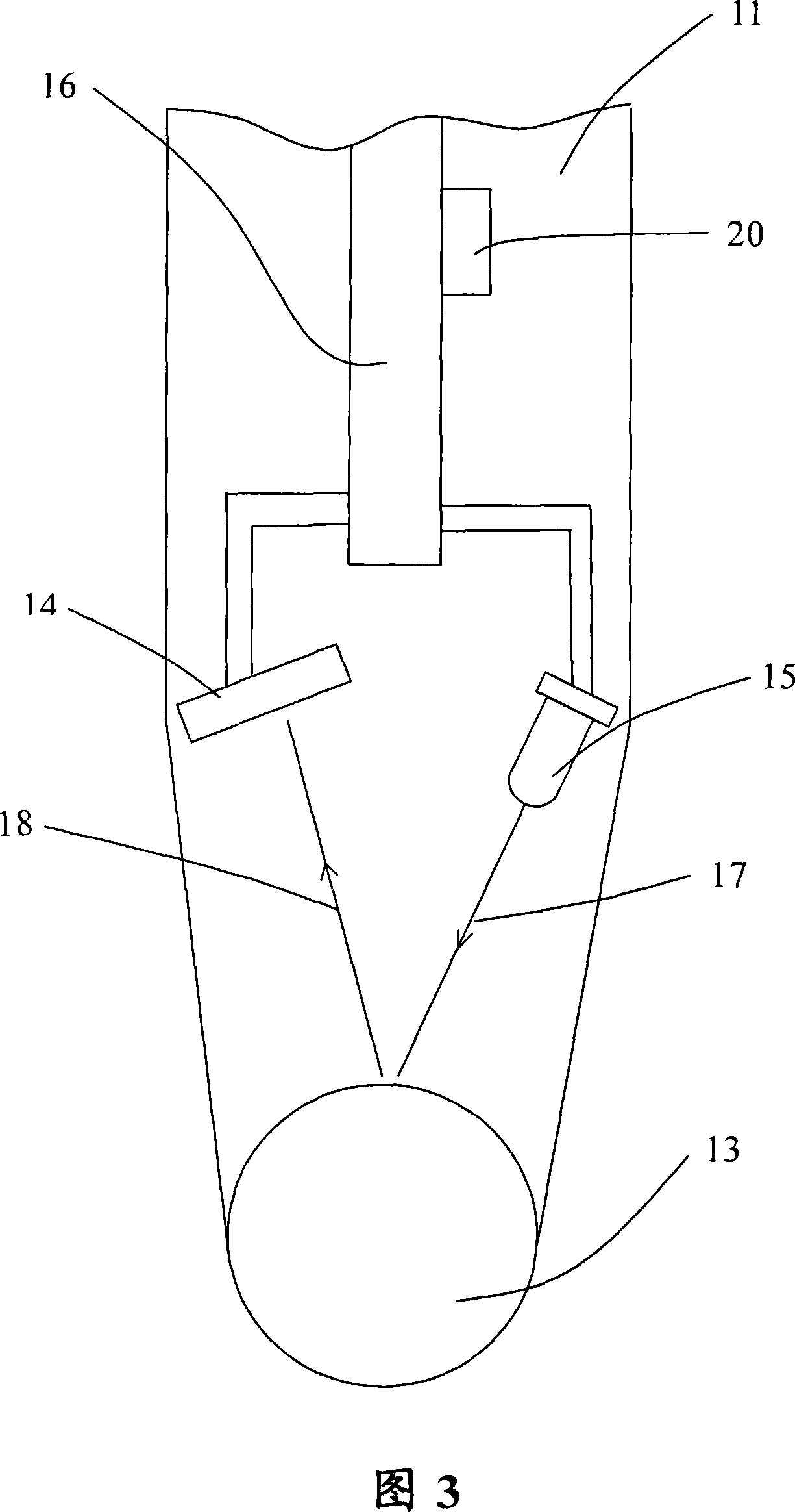
[0026] Fig. 2 and Fig. 3 are structural schematic diagrams of a specific embodiment of the present invention. It describes an optical motion sensing device 10 with pen pointing and data entry functions. The motion sensing device 10 can be connected with a computer as a pointer and cursor control device, such as a mouse, to realize control and input functions, such as a desktop or a portable computer, etc.; it can also be connected with a mobile communication device to realize ...


PUM


Abstract

A motion sensing device, relative to a surface motion, is used to control screen cursor. The sensing device consists of a main part if a pen and an optical trackball situated at the front of the part. A luminescent device and a photographic device are situated inside the main part and several buttons outside. The photographic device has an image detecting array and a signal processing unit. The optical trackball, situated inside the main part, is used to reflect the light sent from the luminescent device to the photographic device. When the motion sensing device moves at the surface and the optical trackball turns, the image detecting device receives the reflected light with information of the trackball surface. Then the signal processing unit processes and changes the light into control signals so as to control the screen cursor. The device is easy to operate and directs more correctly, improve the application reliability and accuracy.

Description

technical field [0001] The invention relates to a motion sensing device, in particular to a motion sensing device applied in the fields of computers, mobile communications and the like. Background technique [0002] Motion-sensing devices, such as mice, are among the most commonly used computer interface devices. When the user moves the mouse on the work surface, the motion sensing device inside the mouse senses the motion trajectory, thereby controlling the pointer or cursor on the computer screen. Generally speaking, there are two types of motion sensing devices in the prior art: mechanical sensing devices and optical sensing devices. [0003] A mechanical sensing device, such as a mechanical mouse, generally includes a rubber ball located at the bottom of the mouse and two scroll wheels mechanically connected to the rubber ball. When the mouse is moved over the work surface such as a mouse pad or desktop, the rubber ball rotates, and the scroll wheel converts the rotati...

Claims


Application Information

Patent Timeline
IPC IPC(8): G06F3/033G06F3/038G06F3/0354
Inventor 高勇刘建
Owner APEXONE MICROELECTRONICS
Why Eureka
Try Eureka