Lubricating device and lubricating method
A lubricating device and lubricating oil technology, applied in the direction of transmission, differential transmission, engine lubrication, etc.
- Summary
- Abstract
- Description
- Claims
- Application Information
AI Technical Summary
Problems solved by technology
Method used
Image
Examples
Embodiment 1
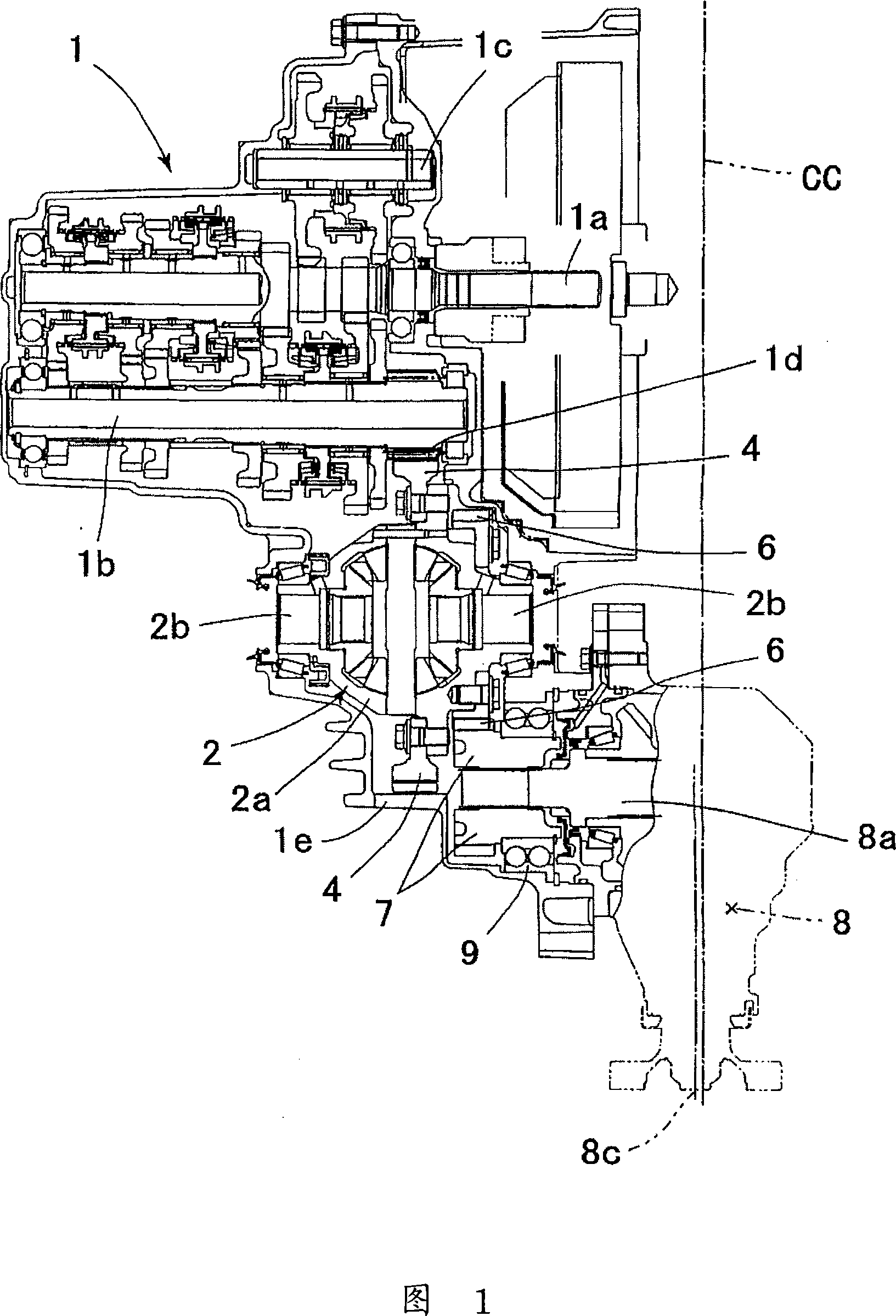
[0067] Figure 1 is a configuration diagram of the entire transmission including the gearbox.
[0068] In the figure, an input shaft 1a for inputting power from the engine side, an output shaft 1b parallel to the input shaft 1a, and an idling shaft 1c for reverse rotation are arranged in the gearbox 1. The multiple gears on 1b transmit the power from the engine to the output shaft 1b at a variable speed ratio.
[0069] An output gear 1d is provided on the output shaft 1b, and the ring gear 4 meshes with the output gear 1d. The ring gear 4 is screwed to the case 2a of the differential device 2 rotatably provided in the case 1e of the transmission case 1 .
[0070] A front wheel side axle 2 b connected to the front wheels is connected to the differential device 2 , and power is transmitted to the front wheel side through the differential device 2 .
[0071] In addition, a transmission gear 6 is fixed to the case 2 a of the differential device 2 by screws, and is formed adjacent...
Embodiment 2
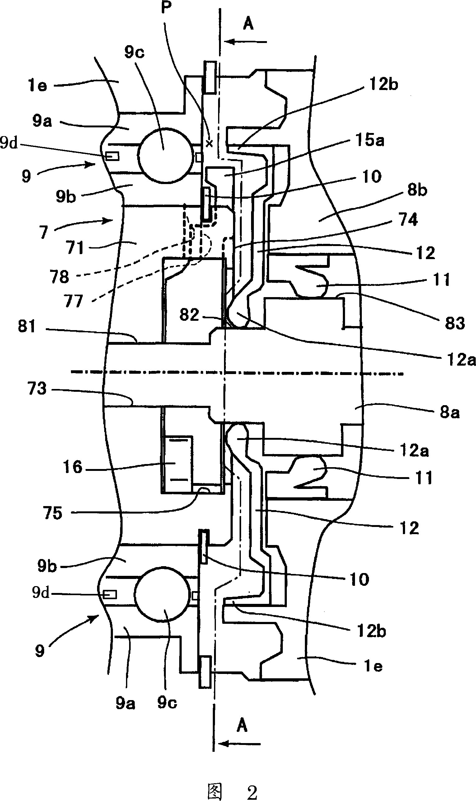
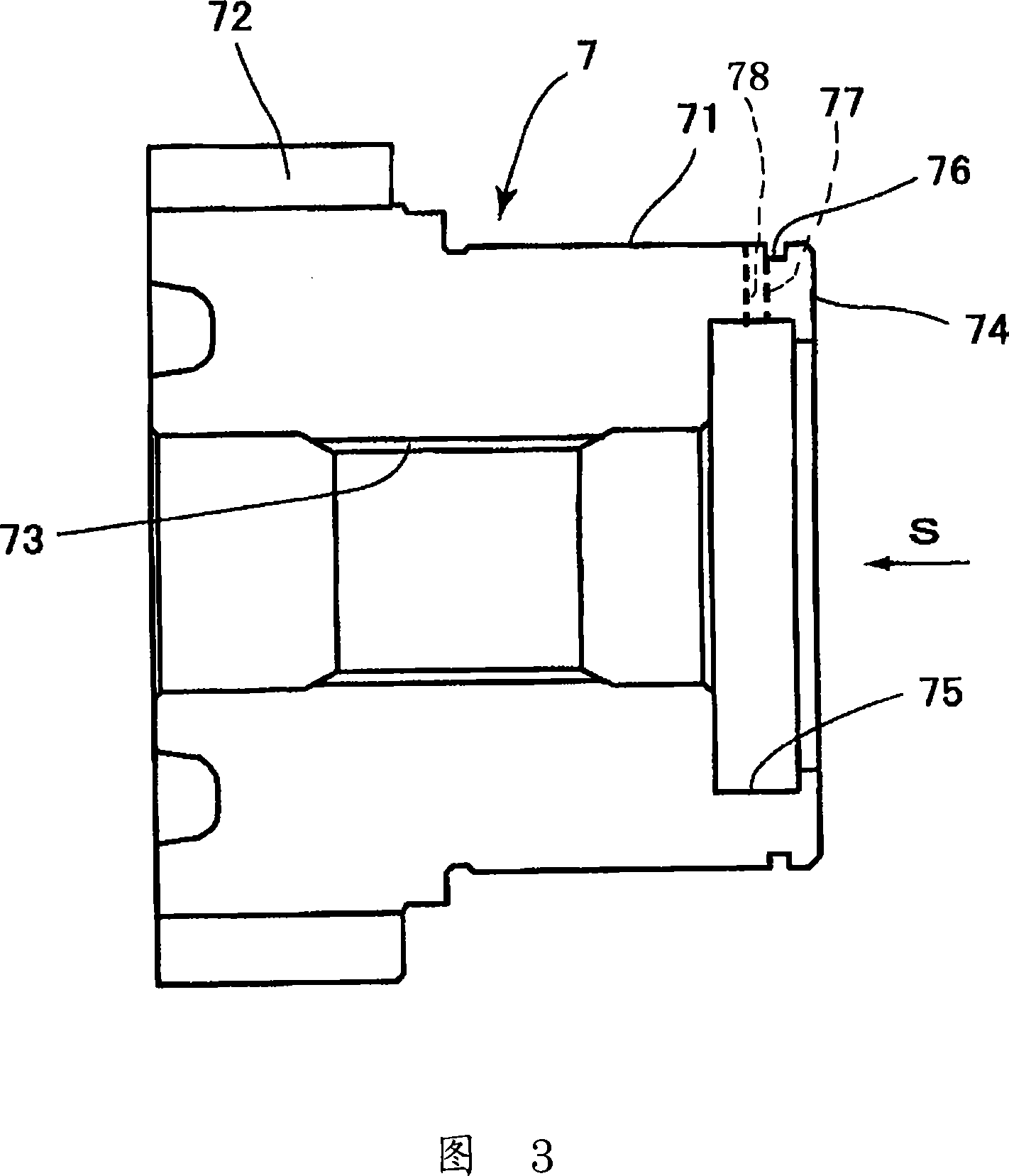
[0096] Hereinafter, FIG. 9 and FIG. 10 are diagrams showing the second embodiment, FIG. 9 is an enlarged sectional structural view of main parts corresponding to FIG. 2 of the first embodiment, and FIG. 10 is a driven gear corresponding to FIG. 3 7 Structural drawing of the section.
[0097] In this example, the radial groove 77 formed on the end surface 74 side of the hub portion 71 of the driven gear 7 is formed in an inclined shape whose depth becomes shallower as the groove bottom surface approaches the inner diameter side.
[0098] That is, the inner diameter side of the radial groove 77 is inclined to the oil seal member 12 side, so that the lubricating oil guided into the radial groove 77 by the extension piece 15a of the scraping member 13 is reliably axially along with the inclination of the radial groove 77. is supplied to the lip 12a of the oil seal member 12.
[0099] The other parts are the same as those of the first embodiment, and the same members are given the...
Embodiment 3
[0101] 11 to 14 are diagrams showing the third embodiment, FIG. 11 is an enlarged cross-sectional structure diagram corresponding to FIG. 2 of the first embodiment, and FIG. 12 is an enlarged cross-sectional structure diagram corresponding to FIG. View in direction V of the scraping member 13 . In addition, FIG. 13 is a configuration diagram of the driven gear 7 viewed from the end face 74 side corresponding to FIG. 4 of the first embodiment. In addition, FIG. 14 is a configuration diagram viewed from the end surface 74 side of the hub portion of the driven gear in a state where the scraping member 13 is assembled.
[0102] In this example, an axially extending portion 16 b extending in the axial direction, that is, toward the lip 12 a side of the oil seal member 12 , is integrally formed on the protruding piece 16 of the scraping member 13 .
[0103] In order to assemble the scraping member 13 so that the axially extending portion 16b protrudes in the axial direction, a notc...
PUM
 Abstract
Description
Claims
Application Information
 - R&D
- Intellectual Property
- Life Sciences
- Materials
- Tech Scout
- Unparalleled Data Quality
- Higher Quality Content
- 60% Fewer Hallucinations
Browse by: Latest US Patents, China's latest patents, Technical Efficacy Thesaurus, Application Domain, Technology Topic, Popular Technical Reports.
© 2025 PatSnap. All rights reserved.Legal|Privacy policy|Modern Slavery Act Transparency Statement|Sitemap|About US| Contact US: help@patsnap.com


