Eureka AIR delivers breakthrough ideas for toughest innovation challenges, trusted by R&D personnel around the world.

Sail-oar combination type wind-light energy source composite type generator and use thereof

A power generation device and a combined technology are applied in the field of wind-solar energy composite power generation devices combined with sails and paddles, which can solve problems affecting photoelectric conversion efficiency, etc., so as to improve wind energy utilization efficiency, increase wind energy momentum, and improve photoelectric power generation energy and photoelectric conversion. The effect of efficiency

Inactive Publication Date: 2012-07-25
马元威
View PDF2 Cites 0 Cited by
  • Summary
  • Abstract
  • Description
  • Claims
  • Application Information

AI Technical Summary

Problems solved by technology

[0003] However, because the application is a single wind-repelling vertical wind-flow wind energy utilization structure, it has certain limitations on the utilization efficiency of wind energy, and because the installed solar cell membrane is always perpendicular to the ground, the angle of receiving sunlight radiation is also limited. Certain limitations also affect the improvement of photoelectric conversion efficiency

Method used


Image

  • Sail-oar combination type wind-light energy source composite type generator and use thereof
  • Sail-oar combination type wind-light energy source composite type generator and use thereof
  • Sail-oar combination type wind-light energy source composite type generator and use thereof

Examples


Embodiment 1

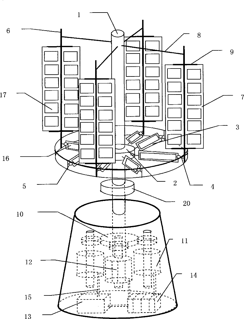
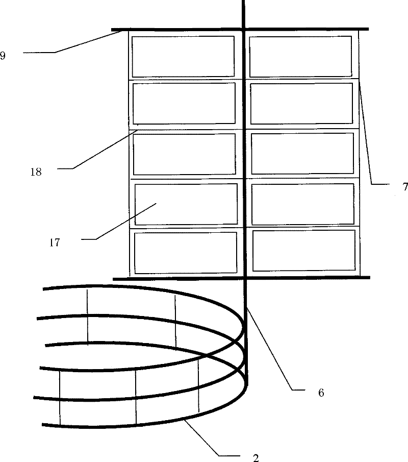
[0041] In this embodiment, the overall structure of the sail-paddle combined wind-solar composite power generation device and the wind power photoelectric structure are shown in the attached figure 1 , attached figure 2 As shown in relevant drawings and descriptions thereof: it has the following structural composition:

[0042] 1. Wind power generation structure: It is a composite of one layer of flat propeller structure and one layer of upright sail structure:

[0043] The flat disc propeller structure is in the form of rectangular blades with vertical axis and horizontal wind flow, and several blades are radially and symmetrically distributed, including: fixed hollow tubular rotating main shaft 1, spoke beam and spoke beam frame structure 2 connected to the main shaft, radiation The blade-shaped members 3 with solar cells on the upper and lower sides installed on the symmetrically distributed spoke beams, the rotating shaft 4 installed on the spoke beams to adjust the angl...

Embodiment 2

[0053] In this embodiment, the overall structure of the sail-paddle combined wind-solar composite power generation device and the wind power photoelectric structure refer to the attached figure 1 , attached figure 2 , attached Figure 8 As shown in relevant drawings and descriptions thereof: it has the following structural composition:

[0054] 1. Wind power generation structure: It is a composite form of a 2-layer flat propeller structure and a 2-layer upright sail structure:

[0055] The flat disc propeller structure is in the form of a vertical axis horizontal wind flow helical blade, and several blades are radially and symmetrically distributed, including: a fixed hollow tubular rotating main shaft 1, a spoke beam and a spoke ring beam frame structure 2 connecting the main shaft, The spiral blade-shaped member 3 with solar cells on the upper and lower sides installed on the radially symmetrically distributed radial beam, the rotating shaft 4 installed on the radial beam...


PUM


Abstract

The invention relates to a sweep-paddle-combined wind driven compound generator and the use of the generator. By a large upright sweep structure, the power energy of the wind is increased, which can drive a large-power generator. And an upright sweep is combined with a wind-energy structure of paddle type flat disc, the utilization efficiency of wind energy is improved while improving the momentum of wind. Another feature with the invention is that, solar batteries are provided both on the upright sweep and the flat paddle; the high scale laying of photocells improves the photoelectric power-generating energy and the photoelectric conversion efficiency. The applications include power generation at blank places for industrial, agricultural, commercial and civil use, power generation for utilities on land, above water and in mountains, and power generation for movable or fixed offshore facilities, ships, and platforms and wind fields for offshore oil wells.

Description

technical field [0001] The present invention relates to the field of energy technology, to be precise, to the technical field of wind power generation and solar power generation. It is a synthesis and intersection of wind power generation and solar power generation technologies. . Background technique [0002] Efficient development and utilization of natural energy technologies is a major issue in the current energy strategy of the international community. Using wind energy to generate electricity through mechanical energy conversion, and using solar energy to generate electricity through photoelectric conversion are relatively mature and widely used natural renewable energy utilization technologies, but these two types of technologies also have their own shortcomings and defects. Wind or windy weather and geographical conditions just can not run, and solar power generation is also difficult to work at night and cloudy time and weather conditions. The similar technical dev...

Claims


Application Information

Patent Timeline
Patent Type & Authority Patents(China)
IPC IPC(8): F03D9/00F03D3/00F03D3/06H02K7/18H02N6/00H02J7/00F03D9/11H02S10/12
CPCY02E10/74Y02E10/72Y02E10/50Y02E70/30
Inventor 马元威
Owner 马元威
Why Eureka
Eureka Blog
Learn More