Fuel injector for internal combustion engine and corresponding method of manufacture

一种燃料喷射器、内燃机的技术,应用在燃料喷射装置、特殊燃料喷射装置、机器/发动机等方向,能够解决减小能力、降低热交换能力等问题

Active Publication Date: 2007-12-19
CENT RICERCHE FIAT SCPA
View PDF0 Cites 8 Cited by
  • Summary
  • Abstract
  • Description
  • Claims
  • Application Information

AI Technical Summary

Problems solved by technology

Such injectors have the disadvantage of preventing the dissipation of the heat generated by the winding, which is generated by the activation of the electromagnet
In fact, the windings are completely covered with plastic material, which greatly reduces their ability to exchange heat with the surrounding environment and, in particular, to transfer heat to the diesel, which flows through the magnetic core disposed below

Method used


Image

  • Fuel injector for internal combustion engine and corresponding method of manufacture
  • Fuel injector for internal combustion engine and corresponding method of manufacture
  • Fuel injector for internal combustion engine and corresponding method of manufacture

Examples


Embodiment Construction

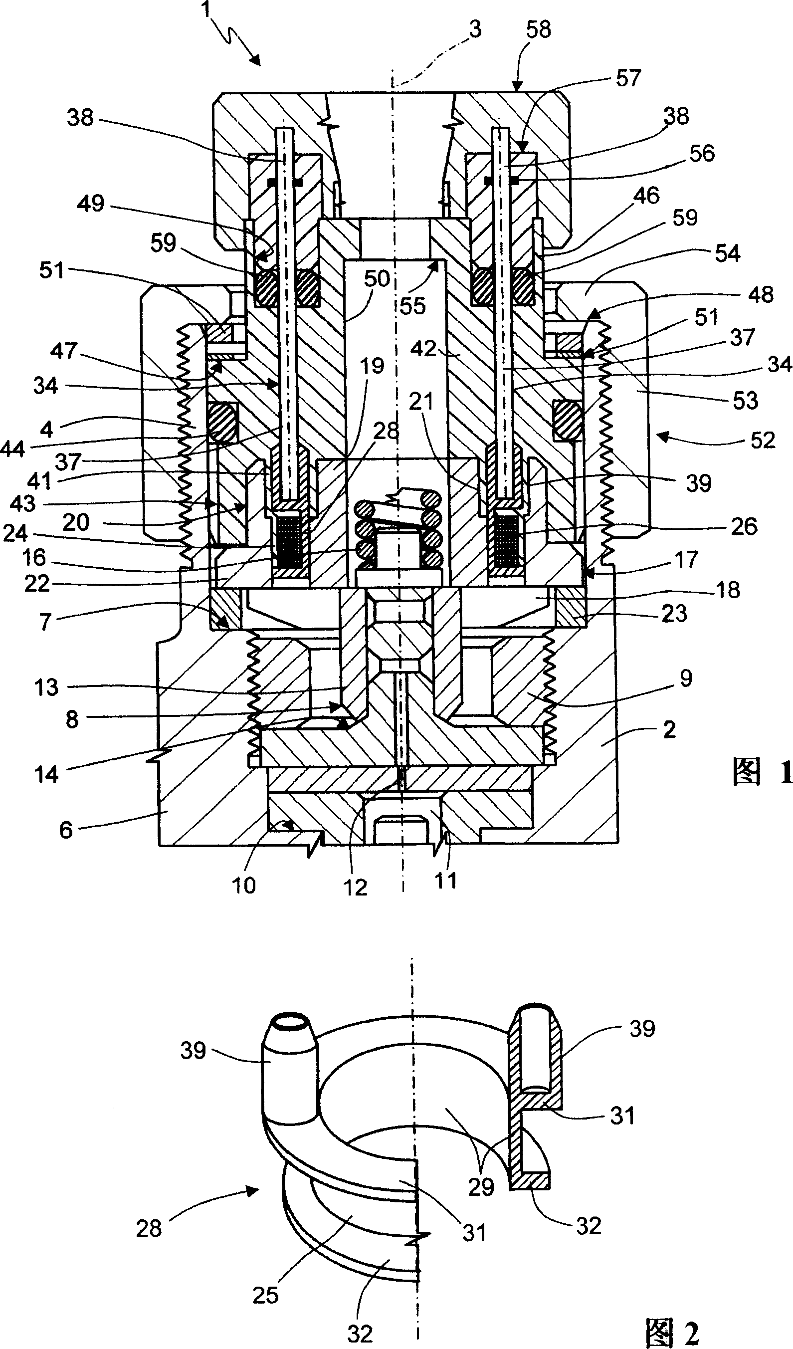
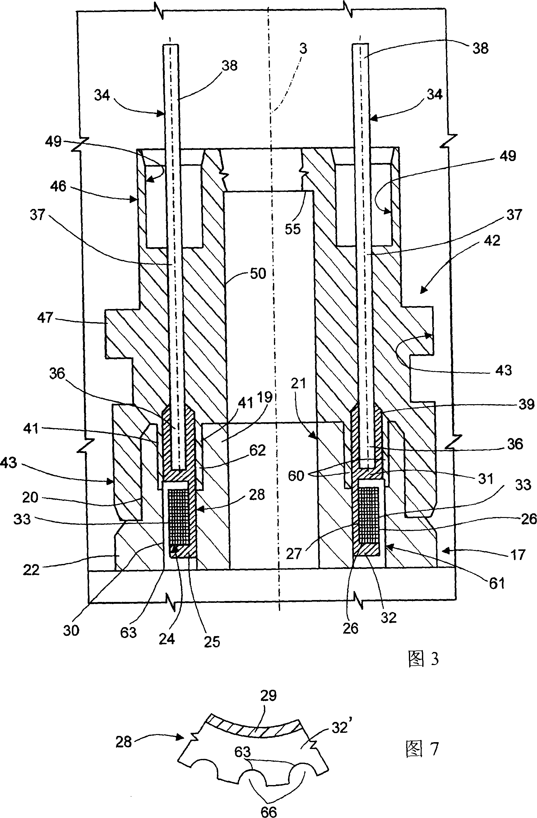
[0025] Referring to FIG. 1 , reference numeral 1 is used to denote generally a fuel injector (injector) for an internal combustion engine comprising a housing formed by a tubular hollow body 2 having an axis 3 . The hollow body 2 starts at the upper free end and contains two tubular extensions 4 and 6 which are radiused by an inner shoulder 7 perpendicular to the axis 3 and constricted in inner diameter. The tubular extension 6 is equipped with a metering valve 8 for injection, and the metering valve 8 is blocked on the boss 10 of the tubular extension 6 through a nut 9 .

[0026] The metering valve 8 comprises a control chamber 11 with a graduated tube 12 for discharging fuel from the control chamber 11 under pressure. The graduated tube 12 is normally closed by a shutter / valve 13 which is pressed against an opposing surface 14 by a coil spring 16 which will be described in more detail below. The scale tube 12 opens under the opposite action of a brake consisting of an elect...


PUM


Abstract

The fuel injector (1) includes a hollow body (2), and a metering valve (8) for injection is installed in the hollow body (2). The metering valve (8) has a graduated tube (12) for controlling the fuel flow. Discharge of cavity (11). The scale tube (12) is usually closed by a baffle (13), which is controlled by an electromagnet (17). The electromagnet (17) includes a magnetic core (19) and an electric winding (26). ), the winding (26) is installed in the annular groove (24) of the magnetic core (19). The winding (26) has an outer cylindrical surface (33), forming a gap (61) with the annular groove (24), so that it can be splashed by the fuel flowing out of the scale tube (12). In particular, the winding (26) consists of a spool (28) having a pair of attachments (39) for supporting a plug (34) for supplying power, said core (19) and said plug At least a portion (37) of (34) is enclosed in a block of non-magnetic material (42). The spool (28) has a cylindrical dome (29) and two planar and parallel flanges (31, 32), one of which is adjacent to one end (36) of the plug (34) and the other flange (31). The rim (32) has a smaller diameter to form a channel (63) for the fuel between the graduated tube (12) and the gap (61).

Description

technical field [0001] The present invention relates to a fuel injector for an internal combustion engine and a method of manufacturing the same. [0002] In particular, the invention relates to an injector comprising a hollow body in which is mounted a metering valve for injection, said valve comprising a graduated tube for discharging fuel from a control chamber. The tube is usually closed by a shutter controlled by an electromagnet comprising a magnetic core and electrical windings, the windings being mounted in annular grooves in the core. Background technique [0003] Usually, the electromagnet is fixed in the hollow body with a suitable fixing system, a block made of non-magnetic material is inserted, the fixing system pushes the magnetic core to the fixing boss of the hollow body, for example, a screw screwed on the hollow body nuts. The electrical coil is wound multiple times and is electrically connected to the two plugs of the power supply. The coil is wound on ...

Claims


Application Information

Patent Timeline
Patent Type & Authority Applications(China)
IPC IPC(8): F02M51/06
CPCY10T137/5987Y10T29/49417F02M51/005F02M63/0015F02M61/168F02M53/04Y10T29/494F02M63/004F02M63/008F02M47/027F02M63/0019Y10T137/0491F02M2200/9015
Inventor 马里奥·瑞可安德里诺·格格里奥内拉菲尔·瑞可塞格奥·斯图彻
Owner CENT RICERCHE FIAT SCPA
Why Eureka
Try Eureka