
Dropping grabbing tamping hammer

A technology of tamper and oil cylinder, applied in the field of tamper, can solve problems such as reducing service life, and achieve the effect of realizing work requirements

Inactive Publication Date: 2007-10-24
张立新
View PDF0 Cites 8 Cited by
  • Summary
  • Abstract
  • Description
  • Claims
  • Application Information

AI Technical Summary

Problems solved by technology

The disadvantage of the existing rammer is that the hammer core of the rammer is always connected with the lifting cylinder or other lifting devices during the lifting and falling process, so that when the hammer core falls rapidly, it drives the corresponding parts of the lifting cylinder or other lifting devices to move quickly, resulting in Adverse effects such as high-speed friction reduce service life

Method used


Image

  • Dropping grabbing tamping hammer

Examples


Embodiment Construction

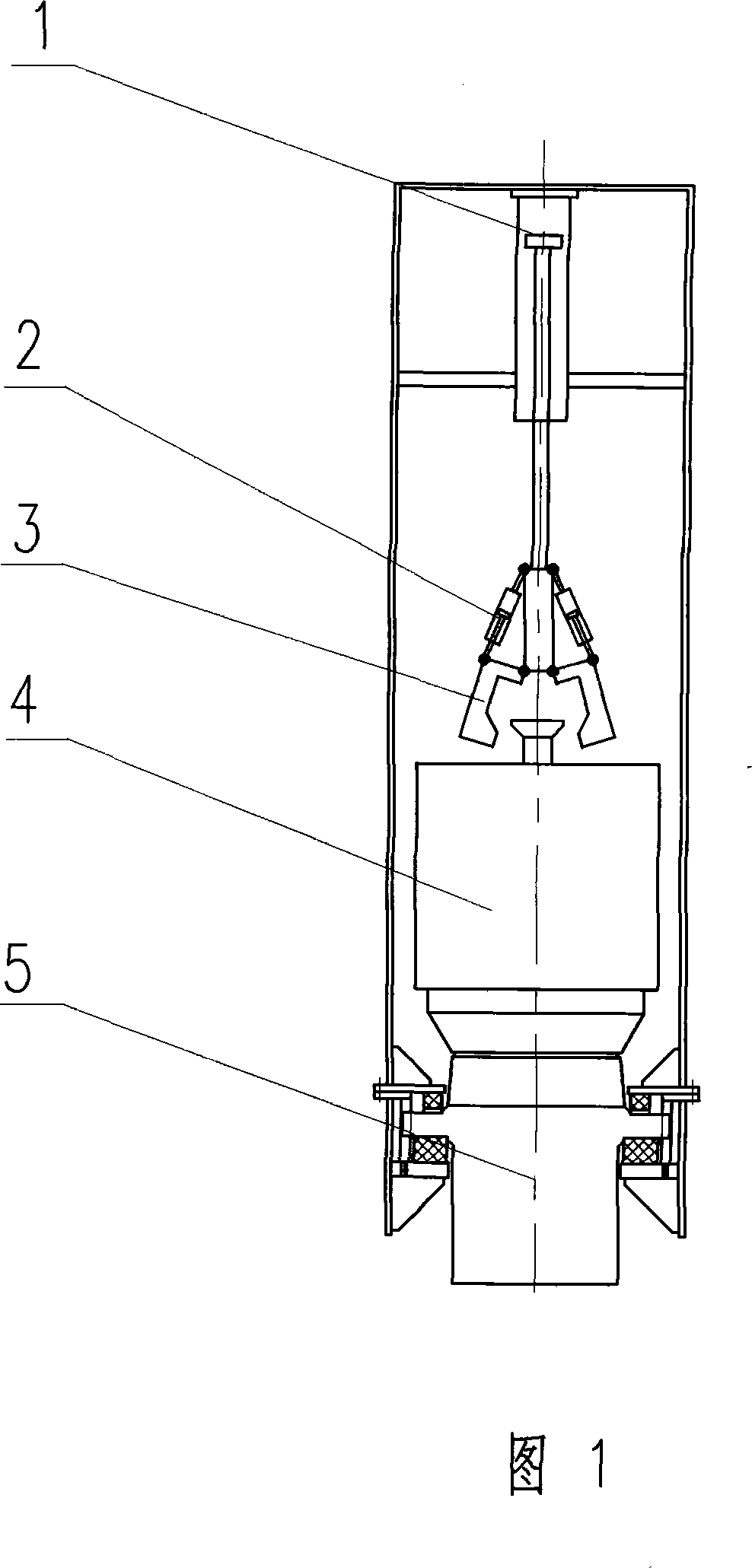
[0009] In the embodiment shown in Fig. 1, the lifting cylinder (1) is tightly coupled with the grasping and disengaging mechanism (3), and the lifting and lowering of the grasping and disengaging mechanism (3) can be realized through the expansion and contraction of the lifting cylinder (1). The expansion and contraction of the opening and closing small oil cylinder (2) can realize the grasping and loosening of the hammer core (4) by the grasping and disengaging mechanism (3). In this way, the grasping and disengaging mechanism (3) can grasp the hammer core (4), then lift it to a certain height, and then loosen the hammer core (4), so that the hammer core can fall rapidly by its own weight to meet the working requirements without driving the lifting The corresponding parts of the cylinder or other lifting device move quickly.


PUM


Abstract

The invention relates to a hammer ram used frequently in forging and construction field. The hammer core is lifted to a certain height by an oil cylinder or other lifting device then falling freely. When it falls, it separates with lifting oil cylinder or other lifting device.

Description

Technical field [0001] The invention relates to a rammer commonly used in forging and construction fields, in particular to a rammer whose hammer core is lifted to a certain height by a lifting oil cylinder or other lifting devices and then falls freely. Background technique [0002] At present, most of the known rammers have their hammer cores raised to a certain height by lifting cylinders or other lifting devices, and then fall down. The disadvantage of the existing rammer is that the hammer core of the rammer is always connected with the lifting cylinder or other lifting devices during the lifting and falling process, so that when the hammer core falls rapidly, it drives the corresponding parts of the lifting cylinder or other lifting devices to move quickly, resulting in Adverse effects such as high-speed friction will reduce the service life. Contents of the invention [0003] In order to overcome the disadvantages of the existing rammer, the present invention provi...

Claims


Application Information

Patent Timeline
IPC IPC(8): B21J7/36B21J7/40E02D3/046E02D7/08
Inventor 张立新
Owner 张立新
Learn More