System and method for generating and utilizing electric power

A power and voltage technology, applied in systems and fields that generate and utilize power, can solve problems such as space consumption and system cost increase

Inactive Publication Date: 2010-05-05
UTC POWER LLC (US)
View PDF5 Cites 0 Cited by
  • Summary
  • Abstract
  • Description
  • Claims
  • Application Information

AI Technical Summary

Problems solved by technology

This can be corrected with large power factor correction capacitors 20, which add to system cost, consume space, and are a possible source for self-excitation, all of which are inappropriate in many installations
These capacitors may require additional bulky series inductors in order to limit the harmonic currents to the capacitors

Method used


Image

  • System and method for generating and utilizing electric power
  • System and method for generating and utilizing electric power
  • System and method for generating and utilizing electric power

Examples


Embodiment Construction

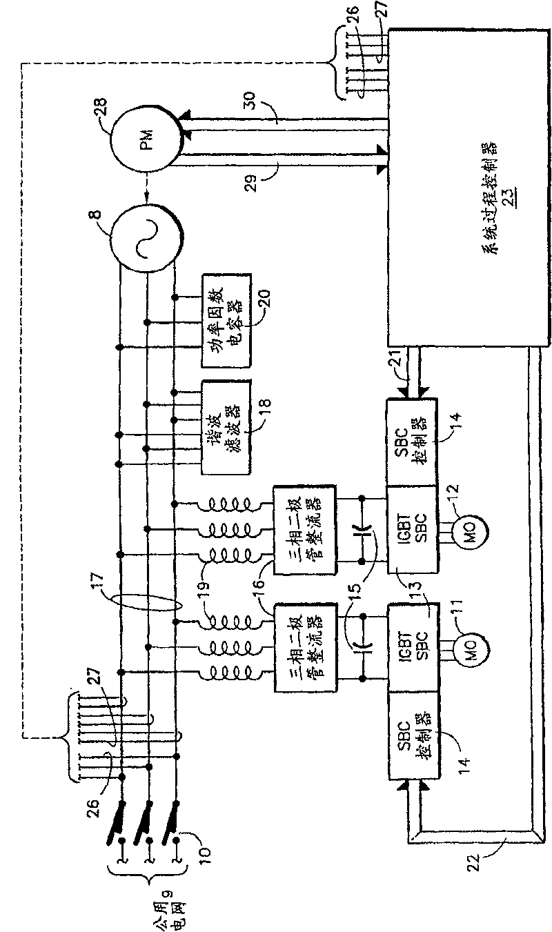
[0014] Referring to FIG. 1 , one known system utilizes a three-phase diode rectifier 16 to provide a DC voltage 15 at the input to an IGBT converter 13 . The converter controller 14 is responsive to signals 21 , 22 from a system process controller 23 . The controller 23 is responsive to current and voltage signals 26, 27, which are indicative of the power generated by the electrical generator 8, including power magnitude and power factor. The controller 23 is also responsive to a signal 29 from the prime mover 28 and provides a control signal 30 to the prime mover. The prime mover may be, for example, a heat recovery device such as an organic Rankine cycle heat recovery device.

[0015] Diode rectifiers draw current from bus 17 in split pulses in antiphase, equivalent to a highly distorted half-sine wave. The inductor 19 brings the current drawn by the rectifier 16 closer to a sinusoidal wave, but not enough to provide an acceptable waveform in sequence on the bus 17 for the...


PUM


Abstract

A prime mover ( 28 ) in a heat recovery system drives an induction generator ( 8 ) which feeds power to a utility grid ( 9 ) through a breaker ( 10 ) but also powers a load including auxiliary induction motors ( 11, 12 ). To provide acceptable waveform and power factor, the auxiliary equipment is driven through IGBT switched bridge converters ( 13 ) by DC voltage ( 15 ) generated by an IGBT switched bridge converter ( 13 a), instead of three-phase diode rectifiers ( 16 ). The switched bridge converter controller ( 14 a) is responsive to a system process controller ( 23 a) which causes the switched bridge controller ( 13 a) to be driven in response to the voltage ( 26 ) and current ( 27 ) on the generator bus ( 17 ). This eliminates the need for harmonic filters ( 18 ) and power factor capacitors ( 20 ) while improving the quality of the power generated. The controller ( 23 a) trips the breaker if the voltage, frequency or power factor is out of limits.

Description

technical field [0001] The present invention relates to supplying power to the utility grid from an induction generator which also supplies its associated variable speed motor drive, such as in a combined heat and power system; Harmonic and power factor, to control the power factor and harmonic components (shape) of the power at the grid interface to be well within the power requirements supplied to the utility grid. Background technique [0002] It has become common for organizations other than power stations to generate electricity and supply electricity to the utility grid, either to receive revenue or to deduct consumer utility bills. Recapturing and utilizing energy (such as heat) that would otherwise be wasted as a by-product of some useful function is becoming commonplace. [0003] In some power generation systems, the manner in which the energy to operate the generators is managed may require auxiliary equipment such as electric pumps and fans. One example is a com...

Claims


Application Information

Patent Timeline
Patent Type & Authority Patents(China)
IPC IPC(8): H02P9/04
CPCH02J3/01H02J3/1892Y02E40/40H02P9/04
Inventor S·J·弗雷德特R·格拉弗
Owner UTC POWER LLC (US)
Why Eureka
Try Eureka