
Foot pedal type pedal force exercise and electricity generation two-purpose machine

A pedal-type, generator technology, applied in the field of fitness equipment, can solve problems such as wasting energy

Inactive Publication Date: 2007-09-19
李清水
View PDF0 Cites 3 Cited by
  • Summary
  • Abstract
  • Description
  • Claims
  • Application Information

AI Technical Summary

Benefits of technology

This technology converts human body's movement into electrical power for storage or usage purposes like illumination.

Problems solved by technology

There are technical problem addressed by this patented design for training machines: current designs require users to use their own body weight when applying resistance during playground activities like cycling or running horses. These devices consume significant amounts of human effort because they only work with one leg at once - making them difficult if there were more than two feet left behind us afterward.

Method used


Image

  • Foot pedal type pedal force exercise and electricity generation two-purpose machine

Examples


Embodiment Construction

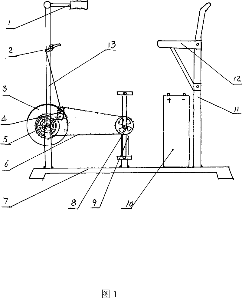
[0008] The technical solution of the present invention will be further described below in conjunction with FIG. 1 .

[0009] It has a front fork frame 13, a pedal frame 9, a rear seat frame 11 on the base 7, a hand-held 1 and a variable speed regulator dial 2 are arranged on the front fork frame 13, and a pedal sprocket wheel is arranged on the pedal frame 9. 8. The seat 12 is installed on the rear seat frame 11, and the characteristic is that a permanent magnet generator 3 is also installed on the base 7 and connected to a battery 10, and a multi-stage variable speed sprocket set is installed on the rotor shaft of the generator 3 5 and variable speed adjuster 4, realize transmission by chain 6 and pedal sprocket.


PUM


Abstract

The application discloses a foot operated type pedal force power generation dual purpose machine, having a front fork frame, a cripple scaffold and a back seat frame on the base, wherein a hand is provided on the front fork frame, and a pedal chain wheel is arranged on the pedal frame, while a seat is mounted on the back seat frame, characterized in that, a permanent magnet type generator is mounted on the base and connected with a storage battery, and a multilevel shifting chain wheel group is arranged on the rotor shaft of the generator, realizing the transmission through the chain and the pedal chain wheel. When the person exercises the pedal force, based on the physical force condition, like the shift of the bike, the speed to ride on the bike is adjusted. During the exercising process, the electric machine rotates in a high speed to generate the electric energy stored in the storage battery. The active effect of the invention is that, the physical ability at the exercise for pedal force can be transmitted into the electric energy stored, which becomes an available energy. If the storage battery of the motor-assisted bicycle is directly used for storage, after being charged, the storage battery can be taken off to mount on the motor-assisted bicycle for riding.

Description


Claims


Application Information

Patent Timeline
Owner 李清水
Learn More