Lift-type silver cabinet
A safe, lift-type technology, applied in the safe field, can solve the problems of heavy, unfavorable anti-theft, occupying indoor space, etc., to achieve the effect of simple and convenient operation and improved safety performance
- Summary
- Abstract
- Description
- Claims
- Application Information
AI Technical Summary
Problems solved by technology
Method used
Image
Examples
Embodiment 1
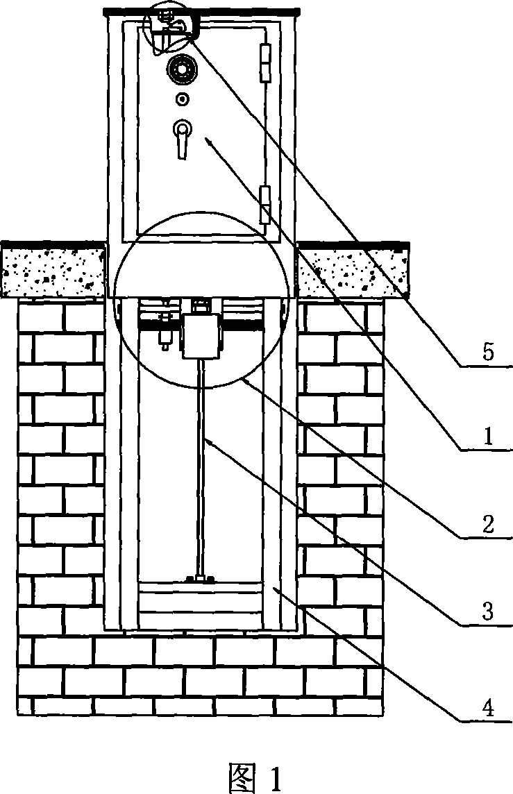
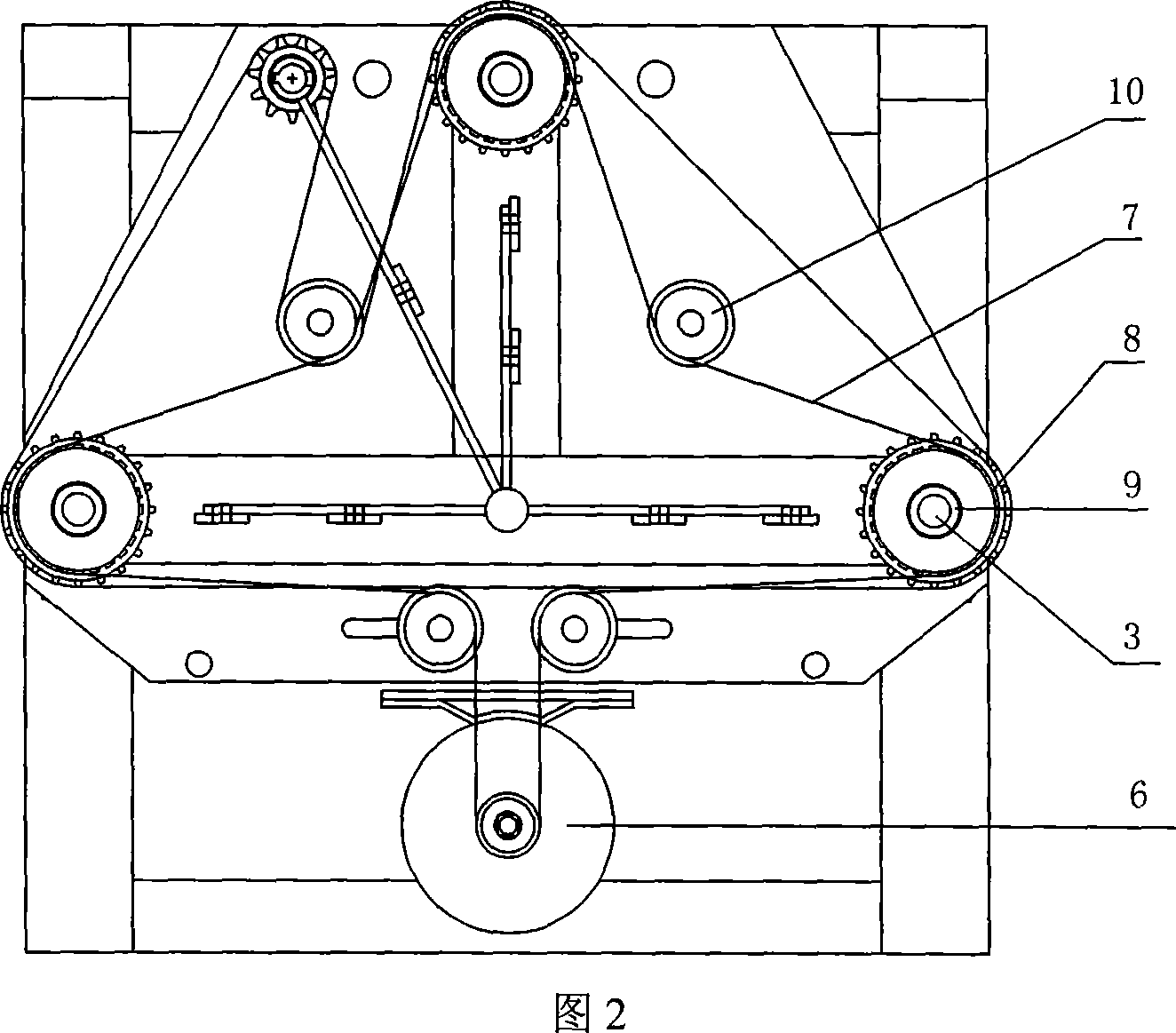
[0016] See Fig. 1 and Fig. 2, a lift-type safe is composed of a safe 1, a transmission mechanism 2, and a frame 4, and the transmission mechanism 2 is composed of a motor 6, a synchronous belt 7, a synchronous wheel 8, a synchronous shaft 9, and a lead screw 3 , the motor 6 is connected to three synchronous wheels 8 through a synchronous belt 7, the synchronous wheel 8, the synchronous shaft 9 and the lead screw 3 are coaxially matched, and a pressure wheel 10 is provided between adjacent synchronous wheels and between the synchronous wheel and the motor . When the motor 6 rotates, it drives the synchronous belt 7 to move, and the four pressure wheels 10 placed in different positions press the synchronous belt 7 tightly, and the synchronous belt 7 can drive the three synchronous wheels 8 to rotate, so that the synchronous movement on the three synchronous wheels 8 The shafts 9 rotate at the same speed, and the three synchronous shafts 9 cooperate with the respective correspond...
Embodiment 2
[0018] In the event of a power outage or failure, the present invention can use the following embodiments to complete the lifting function:
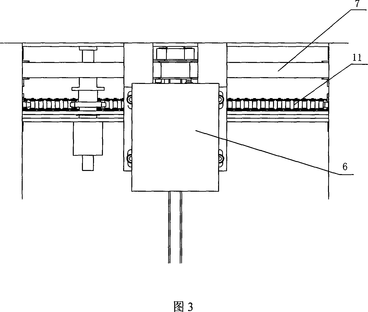
[0019] See Fig. 3, Fig. 4, Fig. 5, a kind of elevating type safe, also has forced elevating device, is made up of force bar 12, force device 17, lever 18, lever axle frame 19, sliding sleeve 20, drag plate 21, sprocket 22, the forcing rod 12 is connected to the lever 18, the two ends of the lever 18 are provided with a sliding sleeve 20, the lever 18 is connected to the carriage 21 through the lever shaft frame 19, and the carriage 21 is connected with the sprocket 22; Connected, the enforcer 17 cooperates with the sprocket 22, the chain 11 connects the sprocket 22, and the sprocket 22 top is provided with a clutch device matched with the groove of the synchronous wheel 8. As shown in Fig. 4, a screw 16 with a hole is provided on the upper part of the mandatory rod 12, and a hook 14 is provided at the lower part of the lock core 13 of th...
PUM
 Abstract
Description
Claims
Application Information
 - R&D
- Intellectual Property
- Life Sciences
- Materials
- Tech Scout
- Unparalleled Data Quality
- Higher Quality Content
- 60% Fewer Hallucinations
Browse by: Latest US Patents, China's latest patents, Technical Efficacy Thesaurus, Application Domain, Technology Topic, Popular Technical Reports.
© 2025 PatSnap. All rights reserved.Legal|Privacy policy|Modern Slavery Act Transparency Statement|Sitemap|About US| Contact US: help@patsnap.com


