
Sheet pile type steel wall and steel pile

A technology for steel sheet piles and steel sheet walls, which is applied to sheet pile walls, water conservancy projects, artificial islands, etc., can solve the problems of inability to use automatic welding machines, different waterproof and reliable functions, and deformation of female joints. The effect of automatic welding, reducing welding cost and reducing water leakage

Inactive Publication Date: 2007-08-29
NIPPON STEEL CORP +1
View PDF10 Cites 3 Cited by
  • Summary
  • Abstract
  • Description
  • Claims
  • Application Information

AI Technical Summary

Problems solved by technology

[0015] In addition, in the invention described in Japanese Laid-Open Patent Publication No. 07-324329 (Patent Document 2), the joint is welded, but it is different from that for discarded water because it is water-proof for buildings, that is, water-proof for groundwater in the foundation. For the water-proofing of waste disposal sites, etc., the degree of water-proofing property only needs to match the degree of drainage facilities installed on the side of buildings, which is not the same as the purpose of the present invention is to seek higher water-proofing property and reliable function.
[0016] In addition, in the invention described in Japanese Laid-Open Patent Publication No. 07-324329 (Patent Document 2), since the female joint material 73 with a special shape is used, it is worried that the female joint material 73 will be deformed when driving in, and it is suspected that the groundwater in the excavated foundation The reliability of the vertical welding of the exposed joints in the wet state or in the water state, in addition, the above method cannot be used with automatic welding machines

Method used


Image

  • Sheet pile type steel wall and steel pile
  • Sheet pile type steel wall and steel pile
  • Sheet pile type steel wall and steel pile

Examples


Embodiment Construction

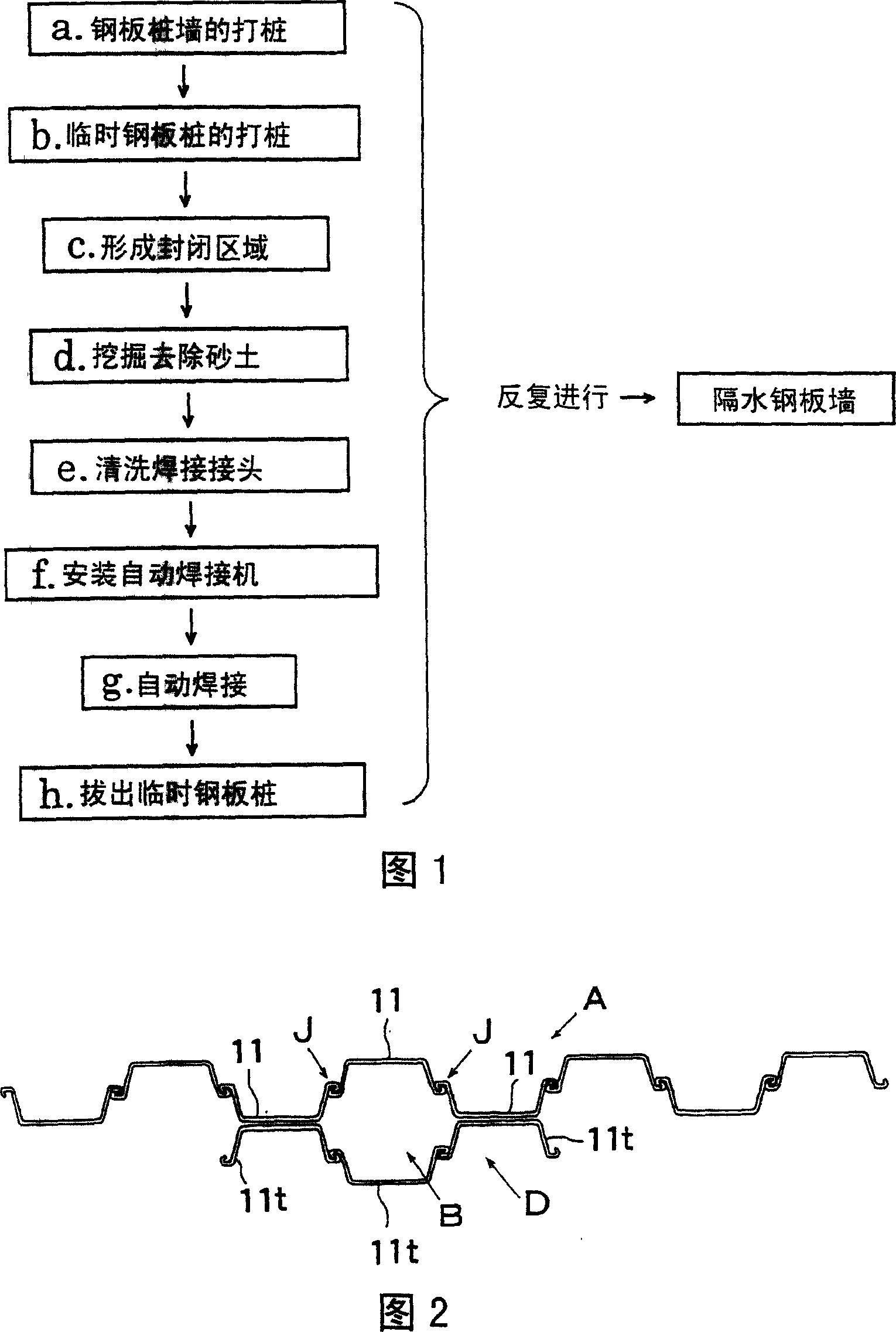
[0163] Fig. 1 shows a flow chart of an example of the construction procedure when using steel sheet piles as steel materials with joints and temporary steel materials as the first invention of the present invention, and work is performed in this order below.

[0164] According to the construction capacity of the steel sheet pile driving machine and the number of machines used, the construction of the steel sheet pile wall starts from any part of the water-resistant steel sheet wall (Fig. 1a).

[0165] In at least one place, temporary sheet piles are driven in (Fig. 1b) to create an area enclosed by a part of the sheet pile wall and the temporary sheet piles (Fig. 1c).

[0166] After excavating to remove sand and soil in the enclosed area (Fig. 1d), the joints of the steel sheet pile walls in the area were cleaned (Fig. 1e).

[0167] Then, install an automatic welding machine (Figure 1f) in the area for automatic welding (Figure 1g).

[0168] After confirming that the water is...


PUM


Abstract

The intention relates to a sheet pile type steel wall and steel sheet piles. The sheet pile type steel wall is formed by connecting a plurality of steel sheet piles with joints at two terminals with each other, wherein: the steel sheet pile has a protruding stage in the same direction of the pile-driving method near the joints of the two terminals, the shape of the transverse cross-section of the joints is not bilateral symmetrical, one side of the joints bucked to each other is formed inwardly with respect to the protruding stage, the other side of the joints is formed outwardly with respect to the protruding stage, in addition, the base of at least one of the joints has a protrusion which can connect a plurality of steel sheet piles with each other in a straight line in a status of the aligning transverse cross-section shape of the steel sheet piles along one direction; welding the protrusions of one side joints and the outer side of the other joints gaplessly along the long direction. Thereby the rotation of the joints of the steel sheet piles is restricted by the protrusions disposed at the base of the joints.

Description

[0001] This application is a divisional application, the application number of its parent application: 200310113838.3, the application date: 2003.10.31, the name of the invention: steel plate wall and its manufacturing method technical field [0002] The invention relates to a sheet pile type steel plate wall and a steel sheet pile suitable for places requiring water isolation, such as waste disposal sites, underground walls of buildings, and road retaining walls. Background technique [0003] Steel sheet piles are often used for retaining walls in the construction of underground structures and temporary embankments in the construction of harbor and water facilities. The reason is that the high-rigidity wall made of steel, a high-quality material, not only can be built in a short construction period, but also has relatively good water-proof performance. [0004] Of course, the steel material itself of the steel sheet pile main body does not pass water at all, but in the fitt...

Claims


Application Information

Patent Timeline
Patent Type & Authority Applications(China)
IPC IPC(8): E02D5/04E02D5/14E02D29/02
Inventor 鹿野裕喜田浩中野启真池田昌弘吉田伦夫
Owner NIPPON STEEL CORP
Learn More