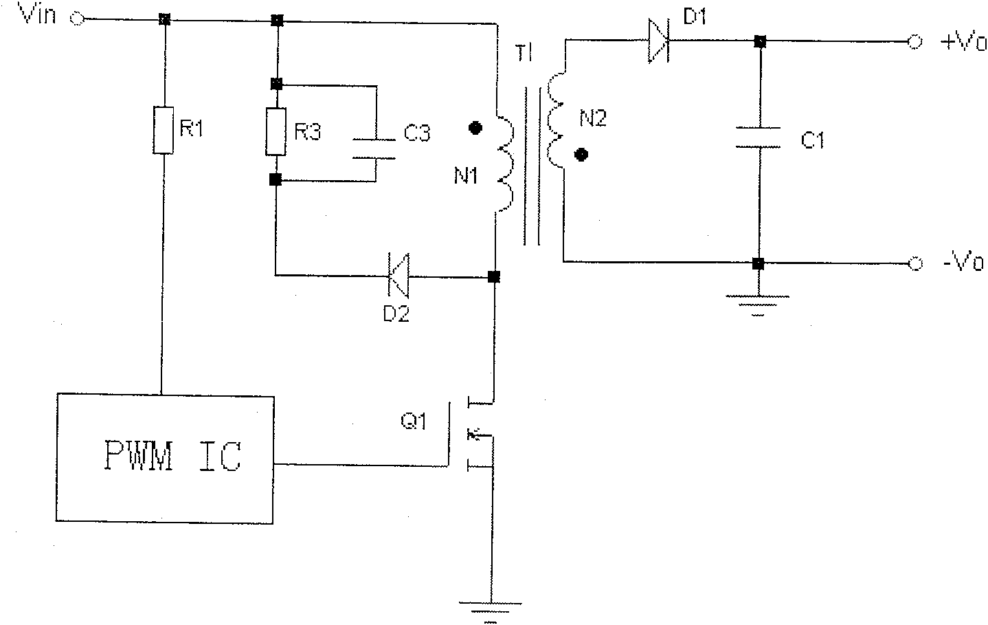
Source electrode driven inverse-excitation converting circuit
A flyback conversion and source drive technology, applied in the output power conversion device, the conversion of DC power input to DC power output, electrical components, etc., can solve the problem that the turn-on loss of the first switch MOS transistor Q1 cannot be controlled, and the energy Loss, circuit efficiency reduction and other problems, to achieve the effect of suppressing sudden short-term spikes, smooth transition of on-off process, and reducing turn-on loss
- Summary
- Abstract
- Description
- Claims
- Application Information
AI Technical Summary
Problems solved by technology
Method used
Image
Examples
Embodiment 1
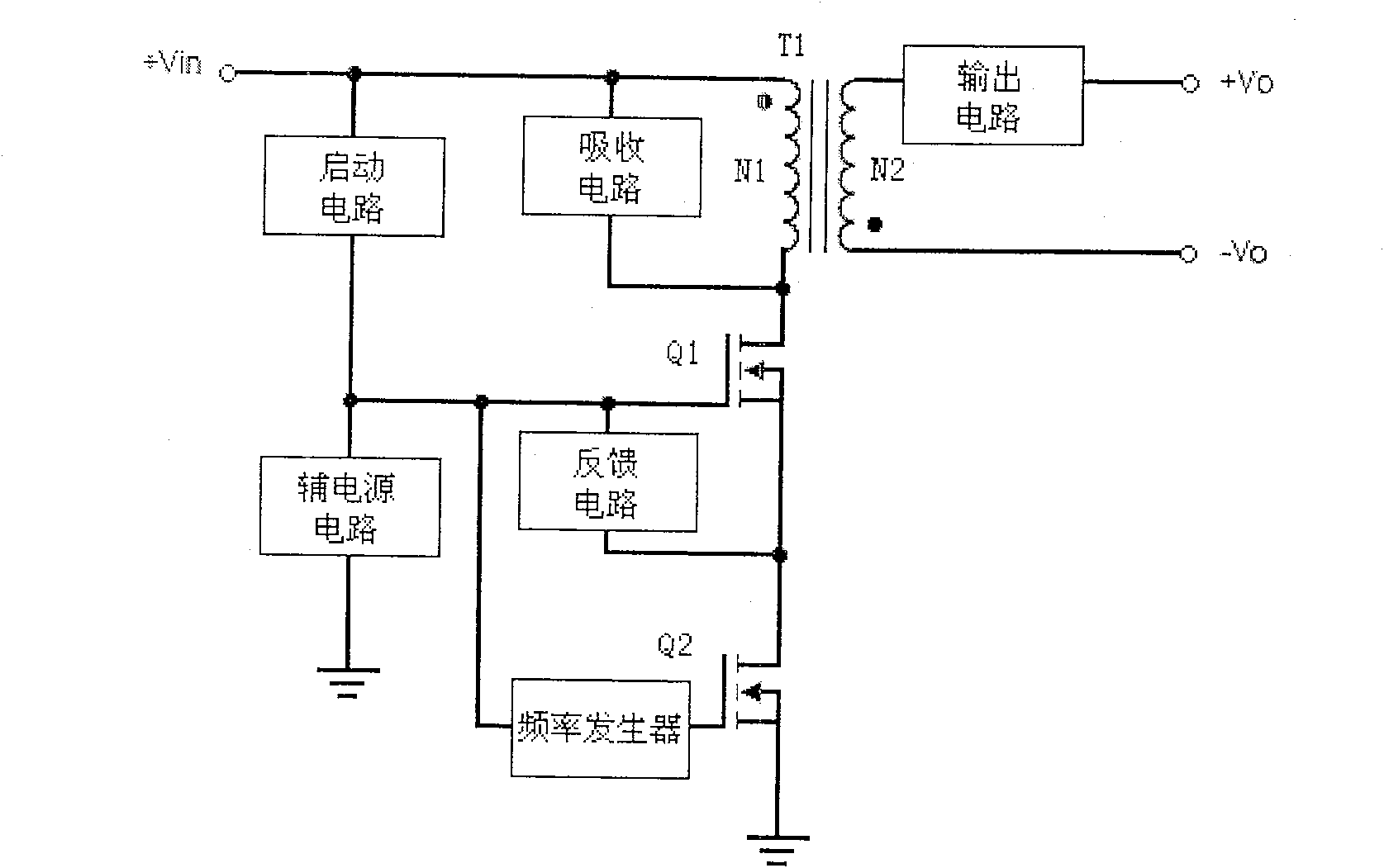
[0029] Such as image 3 , Figure 4 As shown, the present invention adopts the following scheme to achieve the above object: a source-driven flyback conversion circuit, including: a start-up circuit, an absorption circuit, a transformer T1, a first switch MOS transistor Q1, a frequency generator and an output circuit, and the input power Divided into three ways to connect: the first way is connected to the same-named end of the primary winding N1 of the transformer T1, connected to the drain of the first switch MOS transistor Q1 through the different-named end of the primary winding N1 of the transformer T1, and connected in series through the source of the first switch MOS transistor Q1 The drain of the second switch MOS transistor Q2 is grounded through the source of the second switch MOS transistor Q2; the second path is connected to the different terminal of the transformer T1 and the drain of the first switch MOS transistor Q1 after passing through the absorption circuit;...
Embodiment 2
[0041] Such as Figure 6 As shown, the difference compared with Embodiment 1 is that a fifth capacitor C5 is connected in parallel to both ends of the source and drain of the first switch MOS transistor Q1, and the function is to sense the second capacitor C2 of the auxiliary power supply through the leakage of the primary winding N1 of the transformer T1. A DC blocking capacitor is added to the path to improve the dynamic performance of the circuit.
Embodiment 3
[0043] Such as Figure 7 As shown, the difference from the first embodiment is that a fourth capacitor C4 is connected in parallel to both ends of the fourth resistor R4 of the feedback circuit, and the function is to add an isolation to the path from the leakage of the primary winding N1 of the transformer T1 to the second capacitor C2 of the auxiliary power supply. Straight capacitance, improve the dynamic performance of the circuit.
PUM
 Abstract
Description
Claims
Application Information
 - R&D
- Intellectual Property
- Life Sciences
- Materials
- Tech Scout
- Unparalleled Data Quality
- Higher Quality Content
- 60% Fewer Hallucinations
Browse by: Latest US Patents, China's latest patents, Technical Efficacy Thesaurus, Application Domain, Technology Topic, Popular Technical Reports.
© 2025 PatSnap. All rights reserved.Legal|Privacy policy|Modern Slavery Act Transparency Statement|Sitemap|About US| Contact US: help@patsnap.com


