
Non-uniform flexible anchoring baffle pond inverted arch bottom plate structure

A stilling pond and bottom plate technology, applied in water conservancy projects, marine engineering, coastline protection, etc., can solve the problems of anchoring steel bars in the center plate being wasted, easy to yield, and not playing a major role

Inactive Publication Date: 2009-12-09
TIANJIN UNIV
View PDF4 Cites 0 Cited by
  • Summary
  • Abstract
  • Description
  • Claims
  • Application Information

AI Technical Summary

Problems solved by technology

Due to the effect of the "arch" of the stilling pond, the safety factors of the plates that make up the anti-arch floor of the stilling pond are very different. Generally, the safety factor of the center plate is the largest, and the safety factor of the edge plates is the smallest, thus causing When the anchoring bars on other plates yield, the anchoring bars on the center plate still have a large threshold, thus resulting in a waste of anchoring bars on the center plate of the anti-arch floor structure of the stilling pond
[0003] In addition, since the load borne by the anti-arch floor of the stilling pond is mainly borne by the anchor steel bar and the abutment, the anchor steel bar of the existing anti-arch floor structure of the stilling pond cannot bear the large thrust of the arch end, and it is easy to yield , often the anchoring steel bar has already yielded when the arch end force received is small, so that the arch seat in the anti-arch floor structure of the stilling pond does not play a greater role, which is not conducive to anchoring the steel bar and the arch seat The combined stress between the abutment concrete and the overload capacity of the arch structure is not conducive to exerting the compressive characteristics of the abutment concrete

Method used


Image

  • Non-uniform flexible anchoring baffle pond inverted arch bottom plate structure
  • Non-uniform flexible anchoring baffle pond inverted arch bottom plate structure
  • Non-uniform flexible anchoring baffle pond inverted arch bottom plate structure

Examples


Embodiment Construction

[0015] In order to enable those skilled in the art to better understand the solution of the present invention, the present invention will be further described in detail below in conjunction with the accompanying drawings and embodiments.

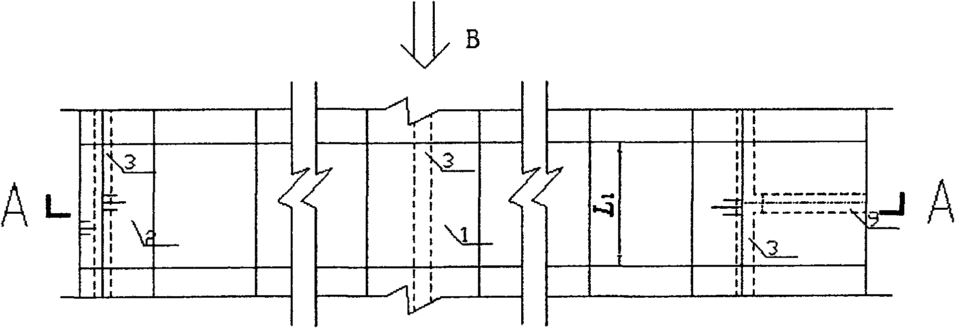
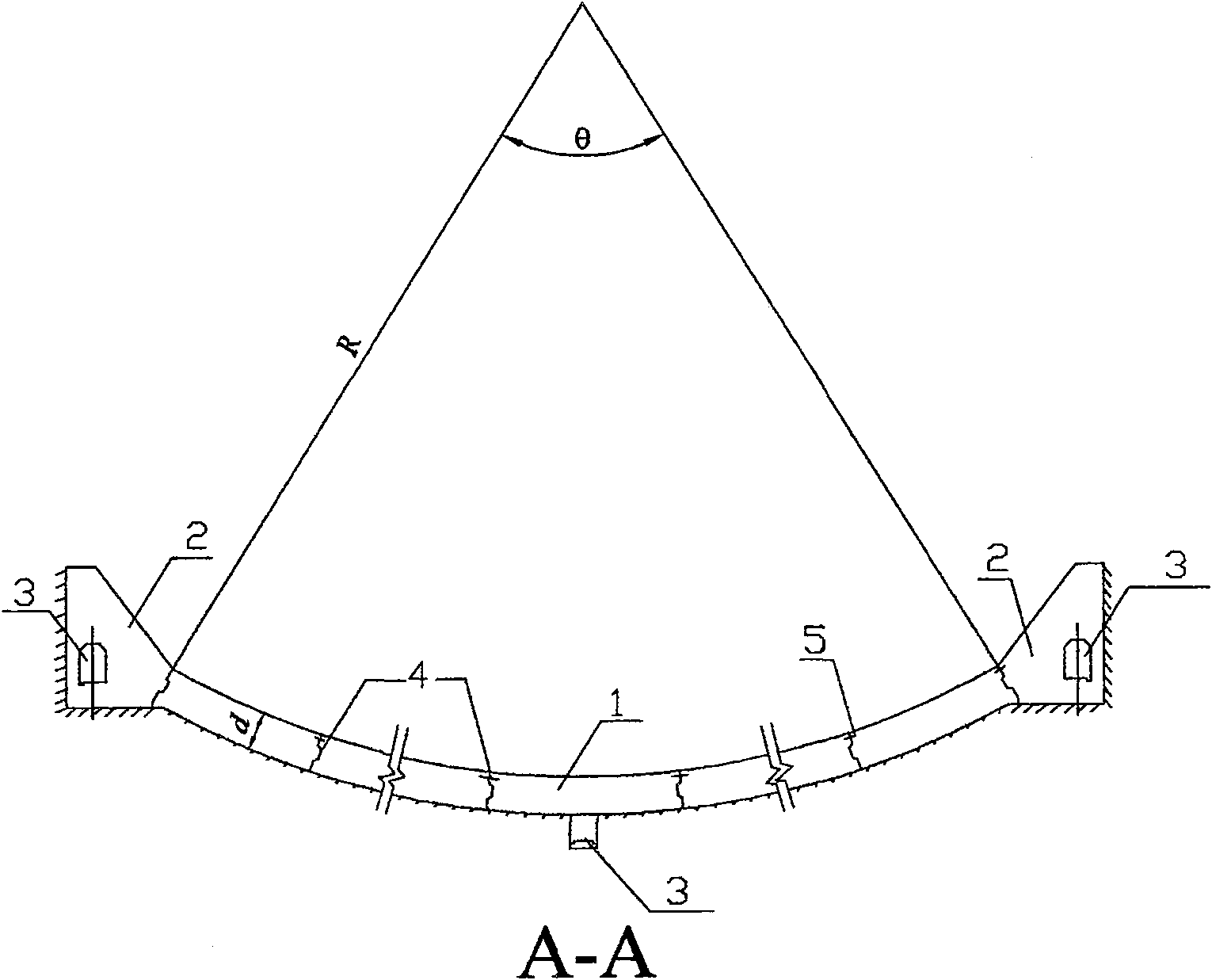
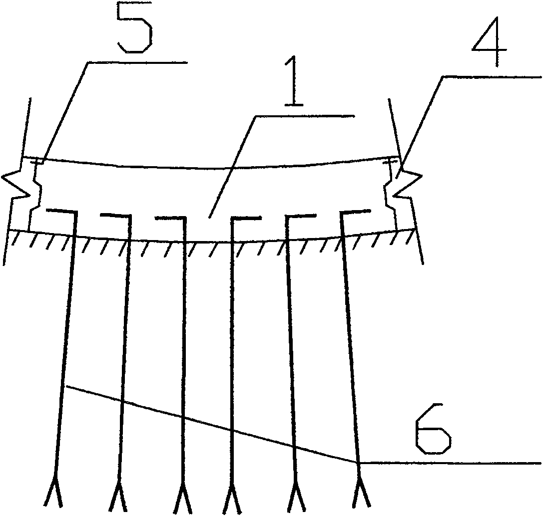
[0016] figure 1 The plane layout diagram of the anti-arch floor structure of the non-uniform flexible anchor stilling pond provided by the present invention, figure 2 The sectional view along the A-A line of the anti-arch floor structure of the non-uniform flexible anchor stilling pond provided by the present invention, image 3 Schematic diagram of the arrangement of anchoring steel bars for the anti-arch bottom plate in the anti-arch bottom plate structure of the non-uniform flexible anchor stilling pond provided by the present invention, Figure 4 It is a schematic diagram of the arrangement of flexible anchoring steel bars on the anti-arch floor structure of the non-uniform flexible anchoring stilling pond provided by the present inven...


PUM


Abstract

The invention discloses an inhomogeneous and flexible anchorage stilling pond anti-arch bottom plate structure, comprising multi-section concrete anti-arch bottom plates (1), concrete abutments (2), and anchoring steel bars (6) distributed laterally along the stilling pond anti-arch bottom plate , the concrete anti-arch floor (1) located at different positions in the horizontal direction of the anti-arch floor of the stilling pond is provided with different amounts of anchoring reinforcement (6) according to the principle that the central plate is small and the edge plate is large, and the anchoring reinforcement (6) is set to a certain Free segment of length. Through the uneven and flexible anchoring of the anti-arch floor structure of the stilling pond provided by the present invention, the amount of anchoring steel bars required by the stilling pond can be effectively reduced while ensuring the safety of the stilling pond. In addition, the inhomogeneous and flexible anchored anti-arch floor structure of the stilling pond provided by the present invention can realize the combined stress between the anchoring steel bar and the arch seat on the anti-arch floor structure of the stilling pond when bearing a relatively large arch end thrust, and It is beneficial to exert the compressive characteristics of the abutment concrete and the overload capacity of the arch structure.

Description

technical field [0001] The invention relates to the technical field of energy-dissipating and anti-scouring facilities for drainage structures, in particular to an anti-arch bottom plate structure of an uneven and flexible anchor stilling pond. Background technique [0002] At present, the anchoring method of the anti-arch floor structure of the stilling pond used in the energy dissipation and anti-scouring project is usually uniform distributed rigid anchorage, and the same amount of anchoring reinforcement is arranged at different positions on the anti-arch floor of the stilling pond. Due to the effect of the "arch" of the stilling pond, the safety factors of the plates that make up the anti-arch floor of the stilling pond are very different. Generally, the safety factor of the center plate is the largest, and the safety factor of the edge plates is the smallest, thus causing When the anchoring reinforcement on other plates yields, the anchoring reinforcement of the center...

Claims


Application Information

Patent Timeline
Patent Type & Authority Patents(China)
IPC IPC(8): E02B8/06
Inventor 练继建马斌刘昉刘喜珠
Owner TIANJIN UNIV
Learn More