
Method, device and relay equipment for detecting synchronous point and switchover point position

A relay device, switching point technology, applied in the direction of synchronization device, selection device, communication between multiple stations, etc.

Active Publication Date: 2009-11-18
DATANG MOBILE COMM EQUIP CO LTD
View PDF3 Cites 0 Cited by
  • Summary
  • Abstract
  • Description
  • Claims
  • Application Information

AI Technical Summary

Problems solved by technology

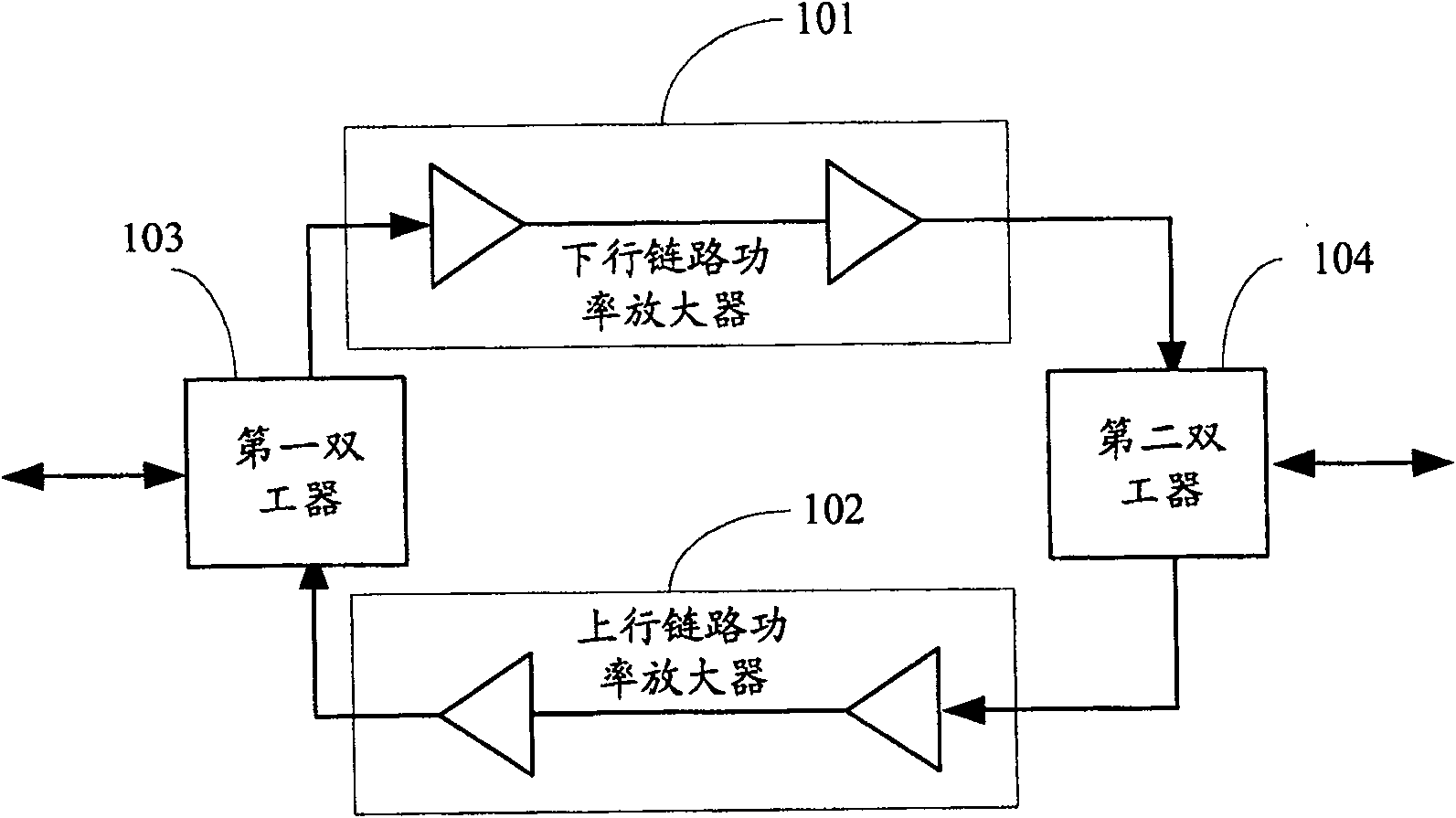
[0011] The present invention provides a method, a device and a relay device for detecting the position of a synchronization point and a switch point to solve the problem in the prior art that the relay device can only obtain the position information of the synchronization point and the switch point from other devices

Method used


Image

  • Method, device and relay equipment for detecting synchronous point and switchover point position
  • Method, device and relay equipment for detecting synchronous point and switchover point position
  • Method, device and relay equipment for detecting synchronous point and switchover point position

Examples


Embodiment 1

[0093] see Figure 4 , which is a flow chart of the method for determining the position of the synchronization point and the switching point in Embodiment 1 of the present invention, and its main implementation process is as follows:

[0094]Step S10, the relay device receives the radio frequency signal sent by the base station or the terminal, performs isolation processing on the uplink radio frequency signal received by the relay device, performs coupling processing on the downlink radio frequency signal received by the relay device, and divides it into two channels, are the first radio frequency signal and the second radio frequency signal, respectively.

[0095] Step S11 , performing power detection processing on the first radio frequency signal and the second radio frequency signal obtained in step S10 respectively, to obtain a first voltage signal varying with the first radio frequency signal and a second voltage signal varying with the second radio frequency signal.

...

Embodiment 2

[0134] see Figure 10 , which is a flow chart of the method for determining the position of the synchronization point and the switching point in Embodiment 2 of the present invention, and its main implementation process is as follows:

[0135] Step S20, the relay device receives the radio frequency signal sent by the base station or the terminal, performs isolation processing on the uplink radio frequency signal received by the relay device, and performs coupling processing on the downlink radio frequency signal received by the relay device.

[0136] Step S21 , performing power detection processing on the radio frequency signal that has undergone coupling processing or isolation processing in step S20 to obtain a voltage signal that varies with the radio frequency signal.

[0137] Step S22, comparing the voltage signal with the preset threshold, when the duration of the voltage signal continuously reaching the preset threshold meets the duration requirement of the downlink pil...


PUM


Abstract

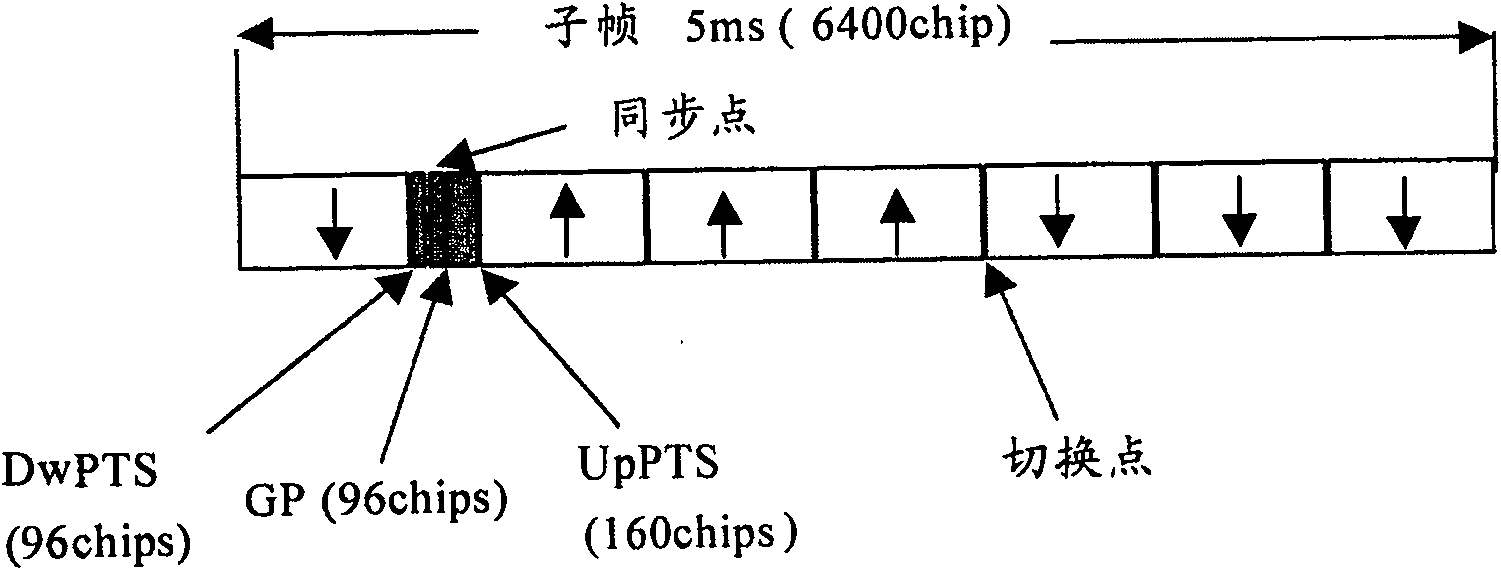
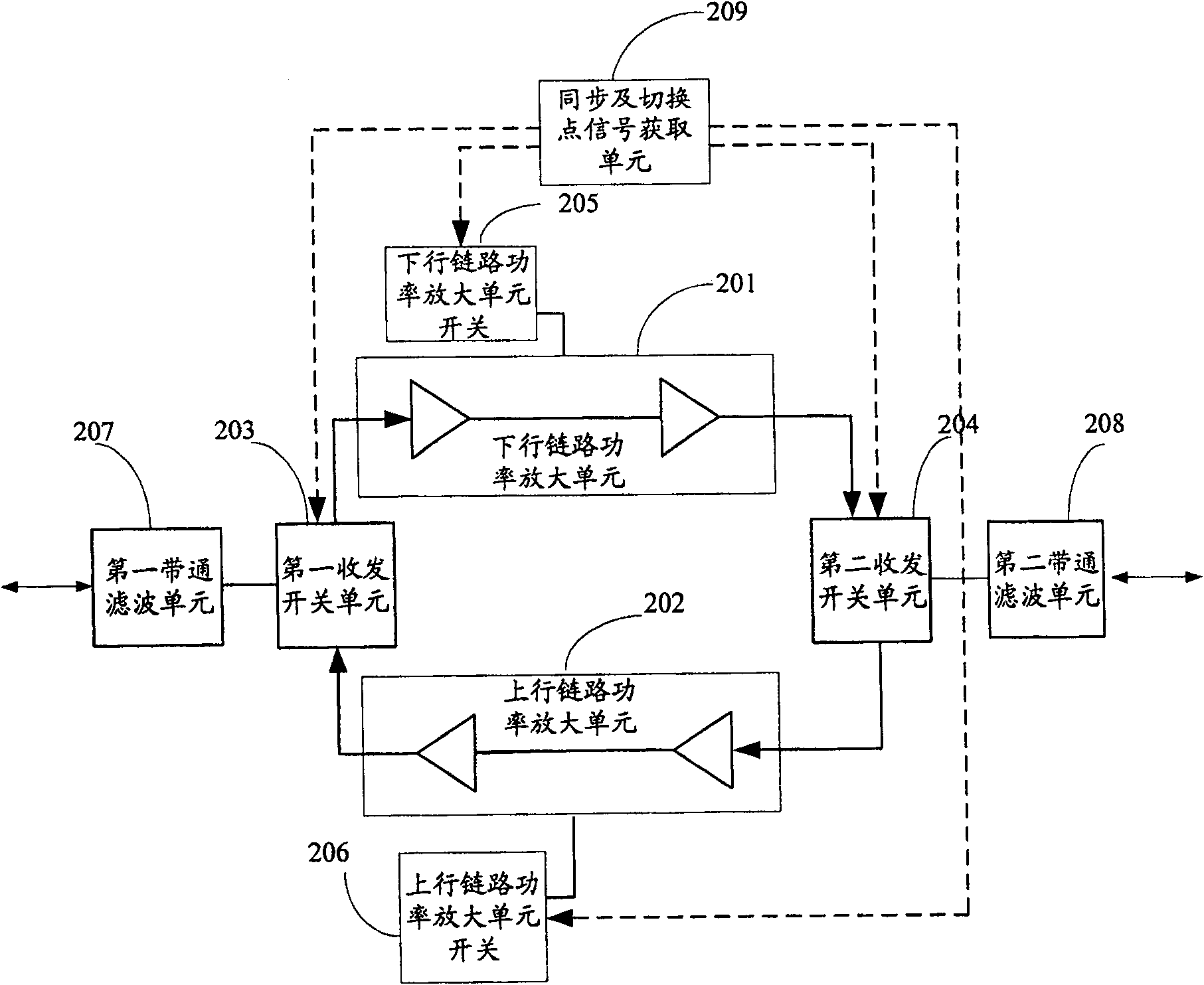
The invention discloses a method, a device and a relay device for detecting the position of a synchronization point and a switch point, which are used to solve the problem in the prior art that the relay device can only obtain the position information of the synchronization point and the switch point from other devices. The present invention couples the radio frequency signal received by the relay device in the downlink direction, performs power detection after isolation processing in the uplink direction, compares the detected voltage signal with a preset threshold, and determines the synchronization point of the current wireless subframe according to the comparison result and the position of the dynamic switch point, and control the transmitting and receiving working state of the relay equipment by using the determined synchronization point and the position of the switching point, so as to realize the dynamic time-division bidirectional amplification of the TD-SCDMA relay equipment.

Description

technical field [0001] The present invention relates to a time division multiplexing wireless communication system, in particular to a method, device and relay equipment for detecting the positions of synchronization points and switching points in the time division multiplexing wireless communication system. Background technique [0002] In a wireless communication system, since the wireless signal of the base station can only cover wireless terminals within a certain range, if the base station needs to cover a larger range, it is necessary to add relay equipment (such as trunk amplifiers, repeaters, etc. Station, etc.), used to relay and amplify the wireless signal sent by the base station to increase the coverage of the base station. [0003] Depending on the working mode of the wireless communication system, the working principle of the applied relay device is also different. Currently, the uplink and downlink working modes in the wireless communication system are mainly...

Claims


Application Information

Patent Timeline
Patent Type & Authority Patents(China)
IPC IPC(8): H04Q7/38H04B7/26H04W56/00
Inventor 王忠勇王大润段滔
Owner DATANG MOBILE COMM EQUIP CO LTD
Learn More