
High precision dynamic gas rotation device for fluting machine

A transmission device and corrugated machinery technology, applied in the direction of mechanical processing/deformation, electrical program control, sequence/logic controller program control, etc., can solve the problems of shortened mechanical life, energy loss, low practicability, etc., to achieve The effect of prolonging the service life of the machine, increasing the operating speed, and high positioning accuracy

Inactive Publication Date: 2009-10-28
李新桥
View PDF8 Cites 0 Cited by
  • Summary
  • Abstract
  • Description
  • Claims
  • Application Information

AI Technical Summary

Problems solved by technology

However, these two kinds of bearings have direct contact between the bearing and the shaft. Such bearings will generate a lot of friction when the machine is running, causing a lot of energy loss; at the same time, friction will shorten the service life of the machine; moreover, the bearing The friction on the machine will also produce a lot of noise, which is harmful to the health of technicians who use this machine
[0003] The gas bearing disclosed in Chinese Patent No. CN 86104100 avoids the direct contact between the bearing and the shaft and can greatly reduce the friction loss, but the bearing cannot bear the axial thrust, and the structure is complicated, the operation is inconvenient, and the practicability is low

Method used


Image

  • High precision dynamic gas rotation device for fluting machine
  • High precision dynamic gas rotation device for fluting machine

Examples


Embodiment Construction

[0014] The present invention will be further described below in conjunction with accompanying drawing.

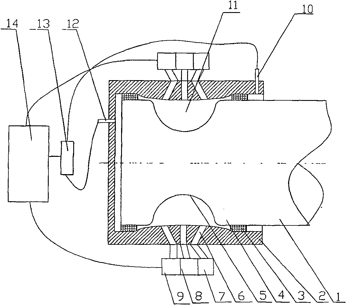
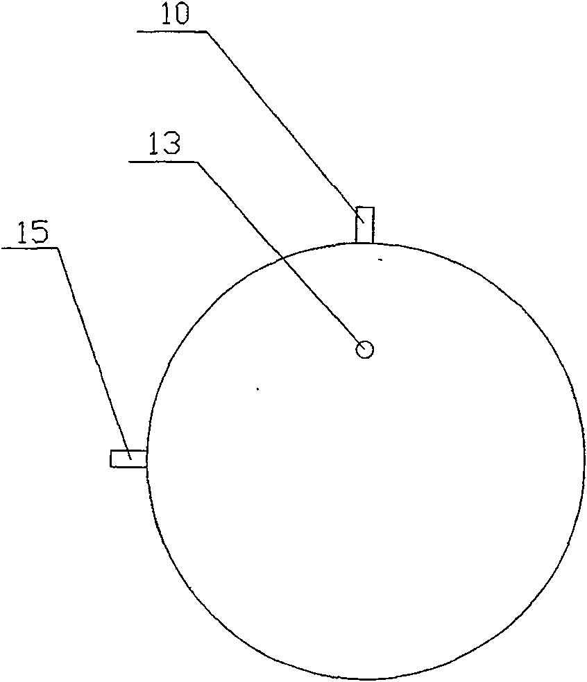
[0015] Referring to the accompanying drawings: the present embodiment includes a shaft 1 and a shaft sleeve 2, and the shaft sleeve 2 is provided with evenly distributed air holes 6, and the air holes 6 are divided into three rows, one of which is perpendicular to the axis of the shaft, and the other two The included angle between the inclined row holes and the radial direction of the shaft is 60°, and the corresponding gas flow control valves 7, 8, 9 are respectively installed on the three rows of vent holes, and rubber seals are installed on the shaft shoulder 4 of the shaft 1 ring 3, the gap between the shaft 1 and the shaft sleeve 2 is filled with the high-pressure gas 11 poured in from the vent hole 6; An axial displacement sensor 12 is installed, a radial displacement sensor 10 is installed in the vertical direction of the axle sleeve 2, a radial displacement sensor 1...


PUM


Abstract

A high-precision dynamic gas transmission device for corrugating machinery, which comprises a shaft and a shaft sleeve, the shaft sleeve is provided with evenly distributed ventilation holes, and a gas flow control valve is installed on each row of the ventilation holes, and the shaft shoulder is provided with a gas flow control valve. A seal is installed, and the gap between the shaft and the shaft sleeve is filled with high-pressure gas injected from the vent hole; the end of the shaft enclosed in the shaft sleeve is provided with an annular groove, and at least three displacement sensors are installed on the shaft sleeve The displacement sensors are respectively electrically connected with the PLC central processing unit through the data acquisition system, and the PLC central processing unit is connected with the gas flow control valve installed on the vent hole. The invention can effectively reduce the running friction, save more than 20% of energy, effectively reduce the noise generated by running, prolong the service life of the machine, and increase the running speed by more than 40%.

Description

technical field [0001] The invention relates to a dynamic gas transmission device, in particular to a high-precision dynamic gas transmission device for corrugated machinery. Background technique [0002] At present, the transmission system of corrugated machinery for manufacturing corrugated paper cores of packaging materials mainly adopts shaft transmission, and the bearings used for shaft transmission mainly include rolling bearings and sliding bearings. However, these two kinds of bearings have direct contact between the bearing and the shaft. Such bearings will generate a lot of friction when the machine is running, causing a lot of energy loss; at the same time, friction will shorten the service life of the machine; moreover, the bearing The friction on the machine also produces a lot of noise, which is harmful to the health of technicians who use this machine. [0003] The gas bearing disclosed in Chinese Patent No. CN 86104100 avoids the direct contact between the b...

Claims


Application Information

Patent Timeline
Patent Type & Authority Patents(China)
IPC IPC(8): B31F1/20G05B19/05
Inventor 曾广胜
Owner 李新桥
Learn More