Control method of electric device and device thereof

A control method and technology of a control device, which are applied in electrical program control, program control in sequence/logic controllers, etc., can solve problems such as limited versatility, and achieve the effects of reducing costs, improving maintenance efficiency, and strong practicability.

Active Publication Date: 2009-07-08
PANASONIC HOME APPLIANCES AIR CONDITIONING GUANGZHOU CO LTD
View PDF3 Cites 0 Cited by
  • Summary
  • Abstract
  • Description
  • Claims
  • Application Information

AI Technical Summary

Problems solved by technology

Therefore, the versatility of the second method is still limited

Method used


Image

  • Control method of electric device and device thereof
  • Control method of electric device and device thereof
  • Control method of electric device and device thereof

Examples


Embodiment 1

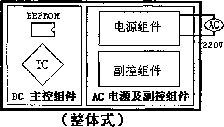
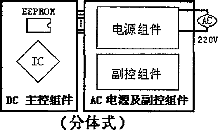
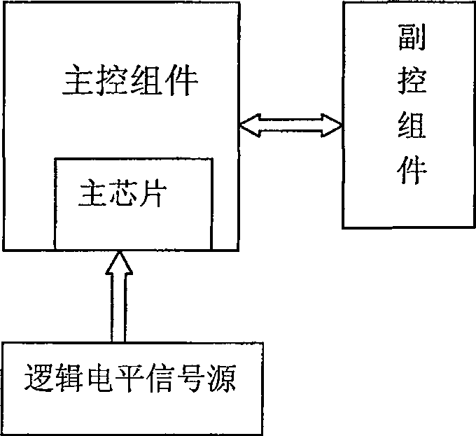
[0038] Such as image 3 , Figure 5As shown, the present invention includes a main control assembly 1, a power supply and an auxiliary control assembly 2, the main control assembly 1 includes a main chip 11, and a variety of air conditioner models (such as wall-mounted, ceiling, pipeline, cabinet, etc.) are integrated in the main chip 11 The control program of the work, and the control program of each specific air conditioner is provided with a corresponding logic level signal, which is convenient for the main chip 11 to call the control program. The power supply and auxiliary control assembly 2 is a collection of control circuits of multiple models (such as single cooling, heating and cooling, and electric heating) in the same model. The power supply and auxiliary control assembly 2 is connected with the internal equipment of the air conditioner (such as fan, heat exchanger, etc.), and controls the operation of the internal equipment of the air conditioner.

[0039] This em...

Embodiment 2

[0044] Such as Figure 6 As shown, the control method adopted in this embodiment is the same as that in Embodiment 1, and the logic level signal source also includes a voltage source, a resistor, and a machine information setting component 4 . The difference from Embodiment 1 is that the negative electrode of the voltage source of the logic level signal source in this embodiment is connected to the pin 15 for reading the logic level signal through the machine information setting part 4, and the positive electrode is connected to the pin 15 through the resistor 14'. connect.

[0045] Therefore, when the power supply connected to the main control unit and the auxiliary control unit are powered by a three-phase power supply and a wall-mounted heating and cooling air conditioner with a horsepower of 1.5, such as Figure 4 As shown, when the logic level signal required to be read by the pin 15 is 1010011011, the first, third, sixth, seventh, ninth, and tenth bits of the output ter...

Embodiment 3

[0047] Such as Figure 7 As shown, the control method of this embodiment, the composition of the logic level signal source and the connection relationship are all the same as those of Embodiment 1. The difference between the two is that the machine information setting part 4 and the connecting part 3 are designed on a printed board superior.


PUM


Abstract

The invention discloses a control method of an electrification device, which includes the steps of a) integrating control programs of multiple models in the main chip of the main control component, and each control program corresponds to a logic level signal; The control component integrates the control circuits of multiple models in the same model; c) the main chip is provided with pins for reading logic level signals from the logic level signal source; d) the main chip The logic level signal calls the corresponding control program to control the power supply and auxiliary control components. The main control component integrates the electrification device programs of various models into the main chip, making the main control component suitable for multiple models; in addition, the power supply and auxiliary control components are completely shared within the same model. The invention further standardizes the control circuit of the electrification device, reduces the cost of mass production, improves the maintenance efficiency of the control circuit, has strong practicability, and can be widely used in electrification devices such as air conditioners and refrigerators.

Description

technical field [0001] The invention relates to the field of control of electrification devices, in particular to a method and device for controlling electrification devices. Background technique [0002] There are two main ways to connect and configure the control circuit of the existing electrification device: the first way is integral, such as Figure 1a As shown, its power supply, sub-control components (that is, the circuit control part that is connected to the internal equipment of the electrification device and controls the operation of the internal equipment), and the main control component (that is, connected with the sub-control component and controls the sub-control component to control the electrification device. circuit control part) are all designed on one electric control board; the second method is split type, such as Figure 1b As shown, the power supply and sub-control components are designed on one circuit board, while the main control component is designe...

Claims


Application Information

Patent Timeline
Patent Type & Authority Patents(China)
IPC IPC(8): G05B19/04
Inventor 徐锦清
Owner PANASONIC HOME APPLIANCES AIR CONDITIONING GUANGZHOU CO LTD
Why Eureka
Try Eureka