
Embedded screw

A screw and implant technology, applied in the field of implant screws, can solve problems such as increasing costs

Inactive Publication Date: 2009-04-22
ULRIKH GMBKH & KO KG
View PDF8 Cites 0 Cited by
  • Summary
  • Abstract
  • Description
  • Claims
  • Application Information

AI Technical Summary

Problems solved by technology

Therefore in practice, there will be a lot of implanted screws for fixing for the operation, by which the vertebral body of different sizes can be taken care of according to the position of the vertebral body in the cervical vertebrae, thoracic vertebrae or lumbar vertebrae, but this increases the operation time for the operation, Cost of location fixation and preparation

Method used


Image

  • Embedded screw
  • Embedded screw
  • Embedded screw

Examples


Embodiment Construction

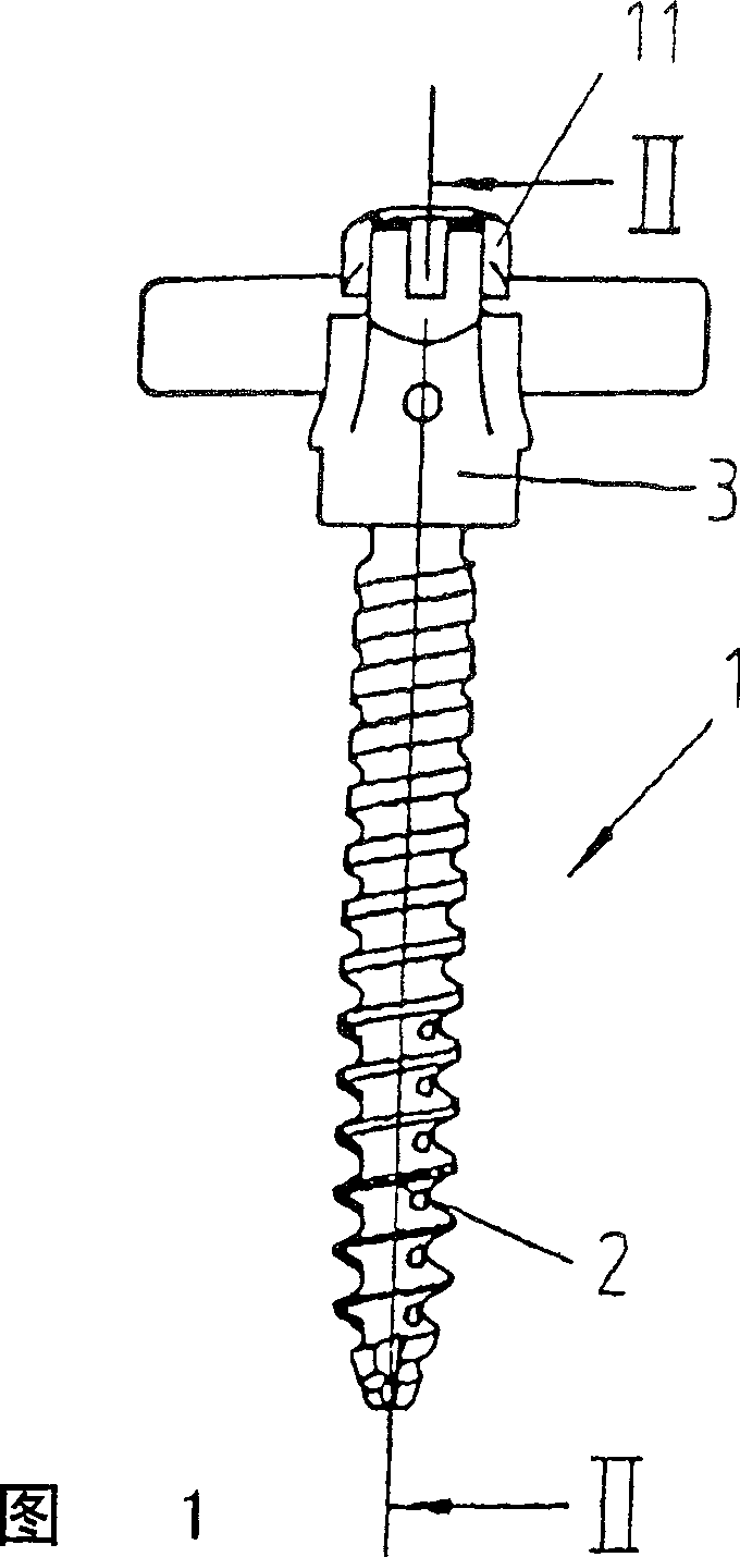
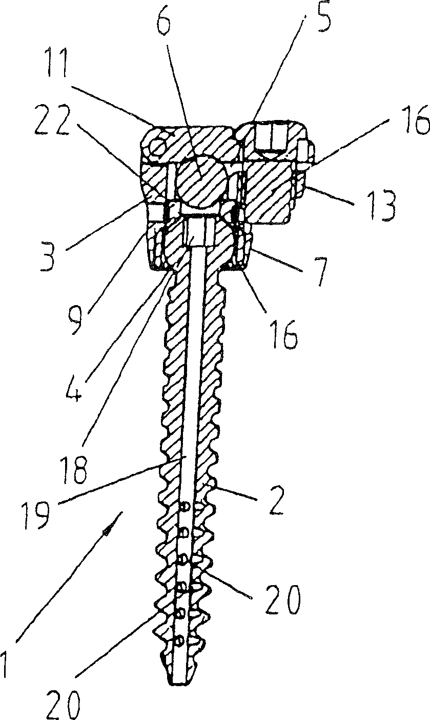
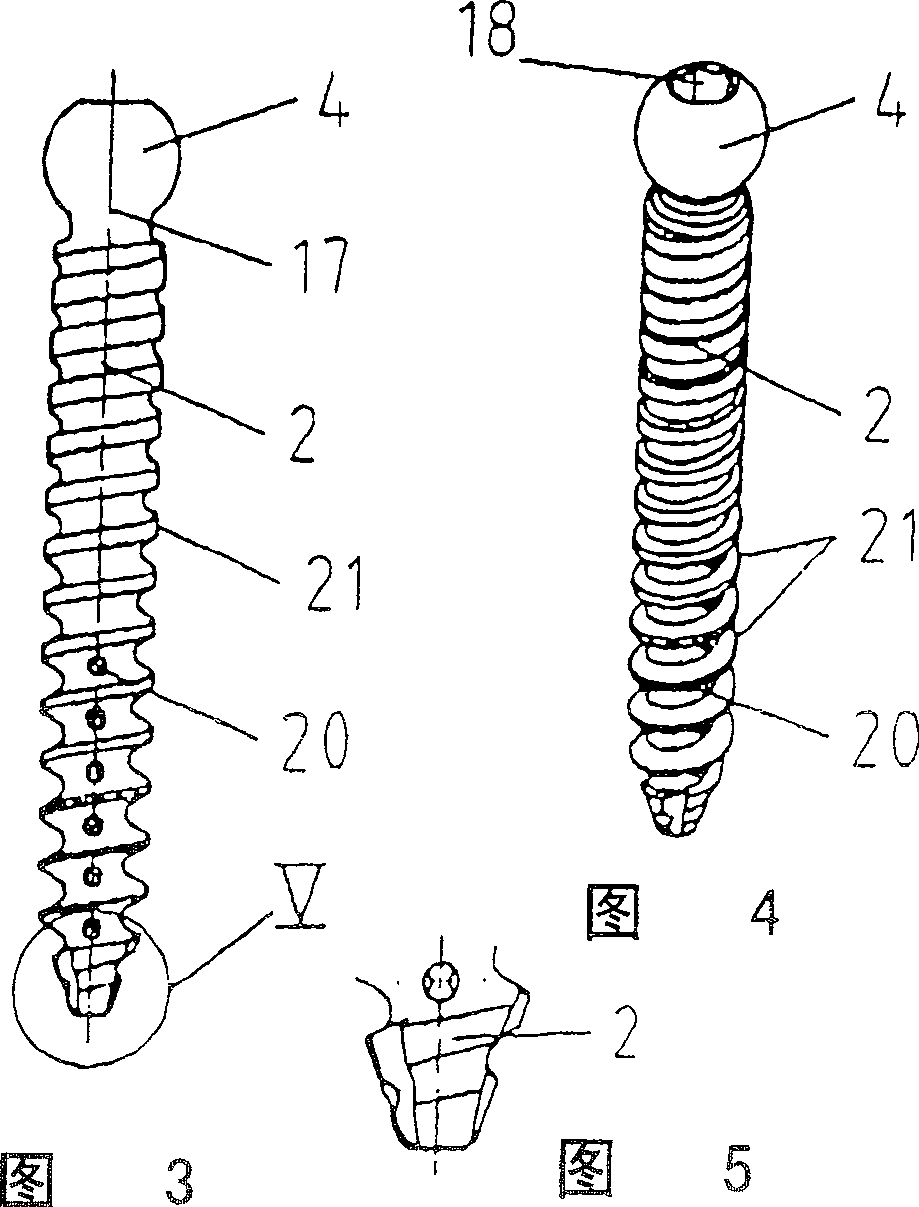
[0042] The drawing shows an implant screw 1 for implants, which consists of a screw shaft 2 and a clip part 3 . On the axial end of the screw 3 is formed a head part 4 which is shaped as a ball head. The clamp part 3 has a clamp receptacle 5 for fastening the connecting rod 6 on the end part 4 , a threaded hole 8 being formed in the clamp base 7 of the clamp part 3 . Furthermore, the clip part 3 has two side legs, wherein a cover 11 is attached to the first side leg 9 via a hinge 10 and projects radially outward from the second side leg 12 laterally away from the first side leg 9 A side leg tongue 13 in which a tongue threaded hole 14 is formed for accommodating a safety bolt 16 passing through the opening 15 of the cover 11 .

[0043] Attach a thread for the end part 4, that is, on the outer surface of the threaded ring 26, a ball socket for the ball head of the end part 4 is formed inside the ring, wherein the inside of the ring can be formed by an inner cone or a hemispher...


PUM


Abstract

The invention relates to a pedicle screw for implants for the correction and stabilisation of the spinal column, comprising a head piece (4), on one axial end of a threaded shaft (2) to which a clamp piece (3) may be connected, comprising a clamp housing (5) for a bar (6) which may be fixed to the head piece (4). A threaded drilling (8) is embodied in the clamp piece (3) for housing a thread provided on the head piece (4).

Description

technical field [0001] The invention relates to an implant screw used as an implant for correcting and stabilizing the spine, having a head portion arranged on the axial end of the screw rod, to which a clamp portion is connected, which has a Clamp receiver for the rod on the end portion. Background technique [0002] Such implant screws are known from practice, and they are used to be screwed into the vertebral body of the spine for degenerative or traumatic diseases of the spine by making at least one rod overlapping a plurality of vertebral bodies along the spine Guiding and anchoring to the spine enables the functions of the spine. For an exact alignment of this rod it is necessary that the position of the implanted screw can be adapted to the rod at least in the contact position, taking into account the anatomically correct position of the implanted screw inside the vertebral body. Therefore in practice, there will be a lot of implanted screws for fixing for the opera...

Claims


Application Information

Patent Timeline
Patent Type & Authority Patents(China)
IPC IPC(8): A61B17/70A61B17/86A61B17/88
CPCA61B17/7035A61B17/863A61B17/8625A61B17/7098A61B17/7037A61B17/7032
Inventor J·苏特克利菲T·麦克M·里奇特N·威尔曼
Owner ULRIKH GMBKH & KO KG
Learn More