
Vertomater

A focimeter and light source technology, applied in the field of focimeter, can solve the problem of rough adjustable range of lighting time

Inactive Publication Date: 2008-12-10
TOPUKON YAMAGATA +1
View PDF4 Cites 0 Cited by
  • Summary
  • Abstract
  • Description
  • Claims
  • Application Information

AI Technical Summary

Problems solved by technology

[0012] However, in the above-mentioned conventional lensmeter, since the adjustable range of the lighting time of the light source is relatively rough, higher precision adjustment is required.

Method used


Image

  • Vertomater
  • Vertomater
  • Vertomater

Examples


Embodiment Construction

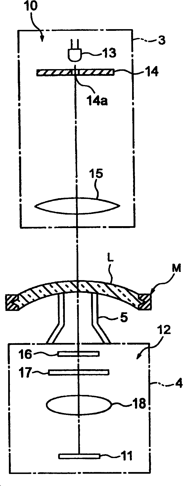
[0046] Next, a preferred embodiment of the lens meter of the present invention will be described with reference to the drawings. figure 1 Shown is a configuration diagram of an embodiment of the lens meter of the present invention.

[0047] The lens meter 100 shown in the figure is provided with a liquid crystal display 2 on the front upper part of the main body casing 1, and at the middle part of the up-down direction of the main body casing 1, an upper frame body part 3 is protrudingly provided to the front. A lower frame body part 4 protrudes from the lower part, and on the upper surface of the lower frame body part 4, a substantially cylindrical lens holder 5 extending toward the upper frame body part 3 is provided. On this lens holder 5, the lens L to be inspected of the eyeglasses M is placed.

[0048] here, as figure 2 As shown, inside the upper frame body part 3, a projecting optical system 10 is provided for projecting the measuring beam (exiting beam) to the lens...


PUM


Abstract

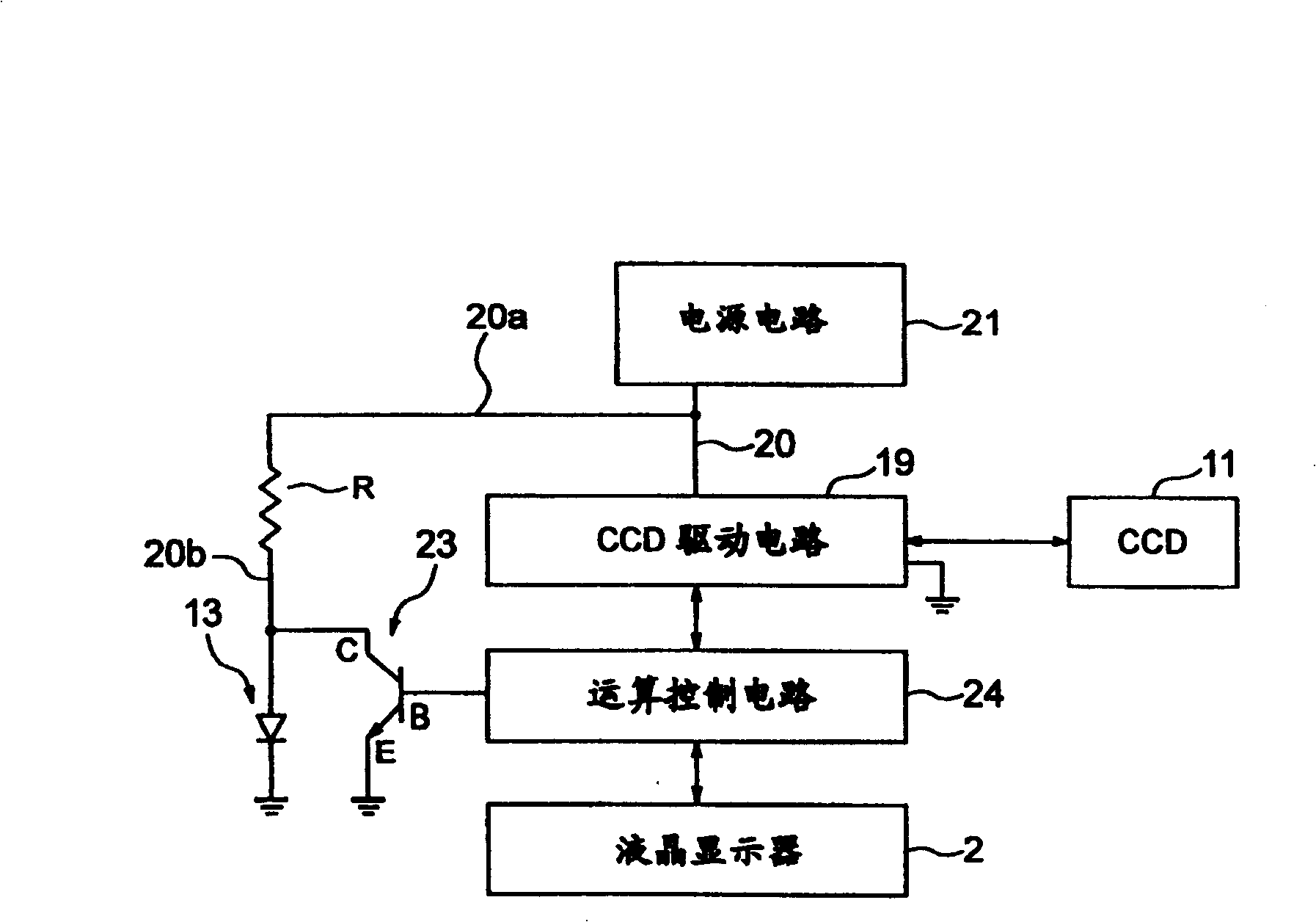
PROBLEM TO BE SOLVED: To improve measurement accuracy of a refraction characteristic of a lens to be inspected by properly adjusting a received light quantity of light from a light source in a lens meter. SOLUTION: In the lens meter 100, the refraction characteristic of the lens L to be inspected is measured by projecting an outgoing beam emitted from an LED 13 (the light source) on the lens L to be inspected, and detecting transmission light transmitted through the lens L to be inspected by a CCD image sensor 11. It is provided with an arithmetic control circuit 24 (a light quantity control means) controlling a lighting time of the LED 13 by a clock signal (a drive signal) of a CCD drive circuit 19 driving the CCD image sensor 11. COPYRIGHT: (C)2006,JPO&NCIPI

Description

technical field [0001] The present invention relates to a focimeter, and in particular, relates to an improvement in the lighting operation of a light source of a focimeter that detects light quantity distribution using a CCD image sensor. Background technique [0002] In the traditional prior art, the focimeter projects the light beam emitted from the light source to the lens to be detected, and uses a light detection device to detect the light distribution of the light passing through the lens to be detected, and according to the detection result, Measure the refractive properties of lenses. [0003] Here, a CCD image sensor is used as a light detection device, and a light emitting diode (LED) is mainly used as a light source. [0004] However, the measurement of the refractive properties of the lens to be detected by the focimeter is performed based on the light intensity distribution (received light intensity distribution) detected by the CCD image sensor as described a...

Claims


Application Information

Patent Timeline
Patent Type & Authority Patents(China)
IPC IPC(8): G01M11/02
CPCG01J1/00G01J2001/448G01M11/0207G01M11/0235G01N21/17
Inventor 国井正辉
Owner TOPUKON YAMAGATA
Learn More