
Magnetically passive position sensor, method for manufacturing the magnetically passive position sensor

A sensor and magnetic technology, which is used in the use of electric/magnetic devices to transmit sensing components, convert sensor outputs, float level indicators, etc. , the effect of high magnetic field strength

Inactive Publication Date: 2008-11-05
CONTINENTAL AUTOMOTIVE GMBH
View PDF5 Cites 1 Cited by
  • Summary
  • Abstract
  • Description
  • Claims
  • Application Information

AI Technical Summary

Problems solved by technology

[0003] A disadvantage of the known position sensors is that the position of the magnet cannot be accurately determined at boundary points within the pivot range of the magnet
When passive magnetic position sensors are used as level sensors in fuel tanks, this leads to inaccuracies that exist just when the tank is almost empty and therefore a particularly high degree of accuracy is required

Method used


Image

  • Magnetically passive position sensor, method for manufacturing the magnetically passive position sensor
  • Magnetically passive position sensor, method for manufacturing the magnetically passive position sensor
  • Magnetically passive position sensor, method for manufacturing the magnetically passive position sensor

Examples


Embodiment Construction

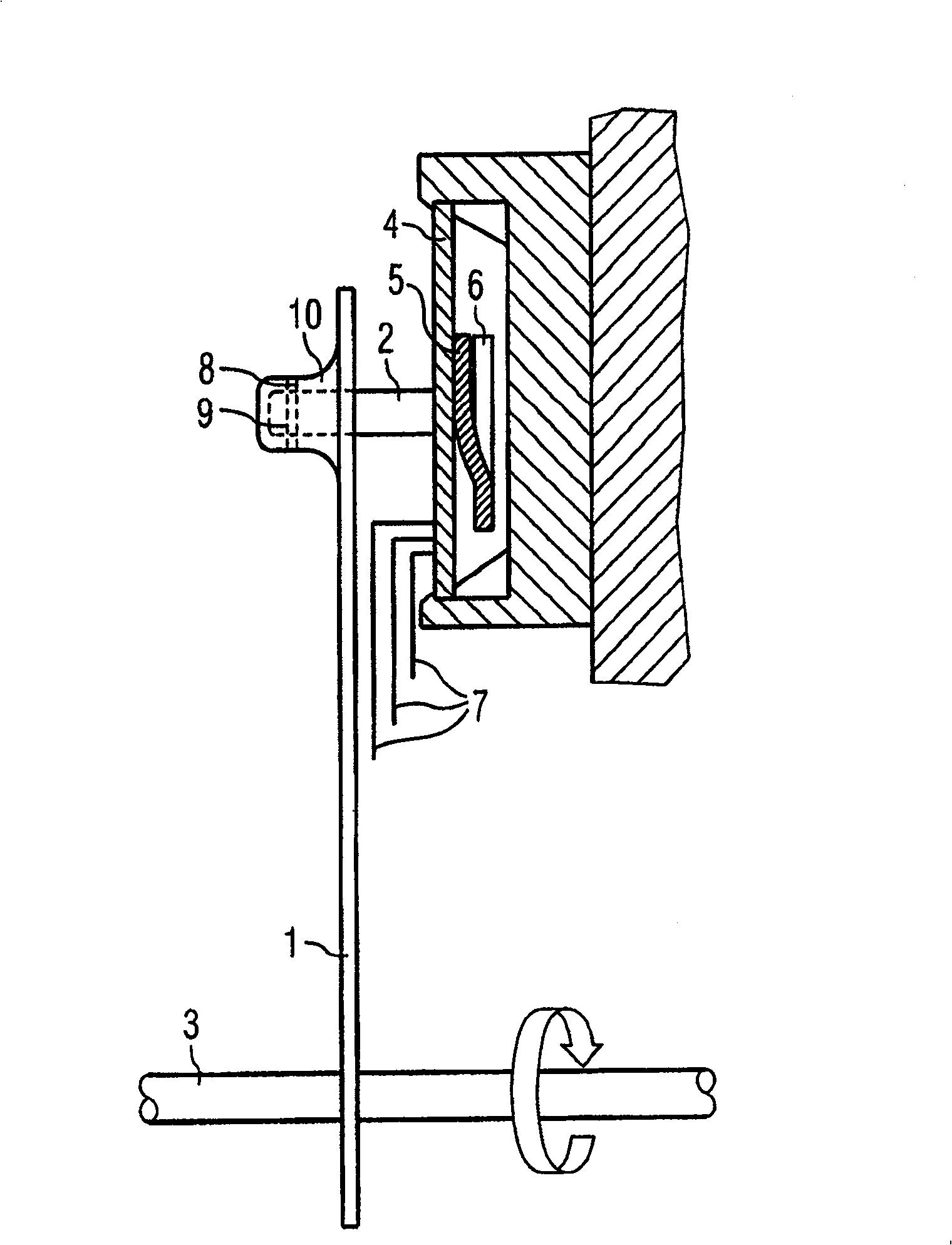
[0016] figure 1 A position sensor is shown with a magnet 2 arranged on a pivot arm 1 . The pivot arm 1 is fixed on the rotation axis 3 . The axis of rotation 3 may be connected to a buoy (not shown) of a liquid level sensor, eg in a motor vehicle fuel tank. The magnet 2 can pivot over the thick film mesh 4 . The magnetic contact spring elements 5 , 6 are arranged on the side of the thick-film mesh 4 facing away from the magnet 2 . The contact spring elements 5 , 6 can be attracted by the magnet 2 and pressed against the thick-film mesh 4 . The thick-film mesh 4 is connected by wires 7 to an electronic unit (not shown) which detects the position of the magnet 2 via contact spring elements 5 , 6 on the thick-film mesh 4 . This position sensor is described in detail in DE 19648539 A1, so that the descriptions therein with regard to possible design and function are hereby incorporated by reference.

[0017] The magnet 2 has a guide polygon 8 , which is arranged on the end sid...


PUM


Abstract

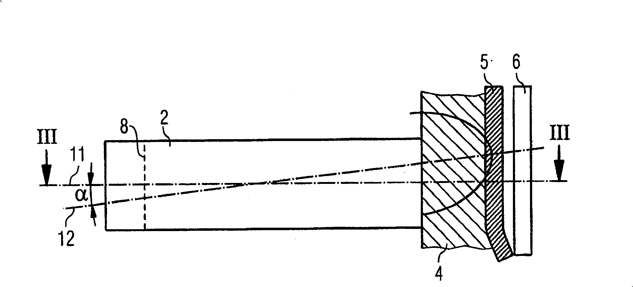
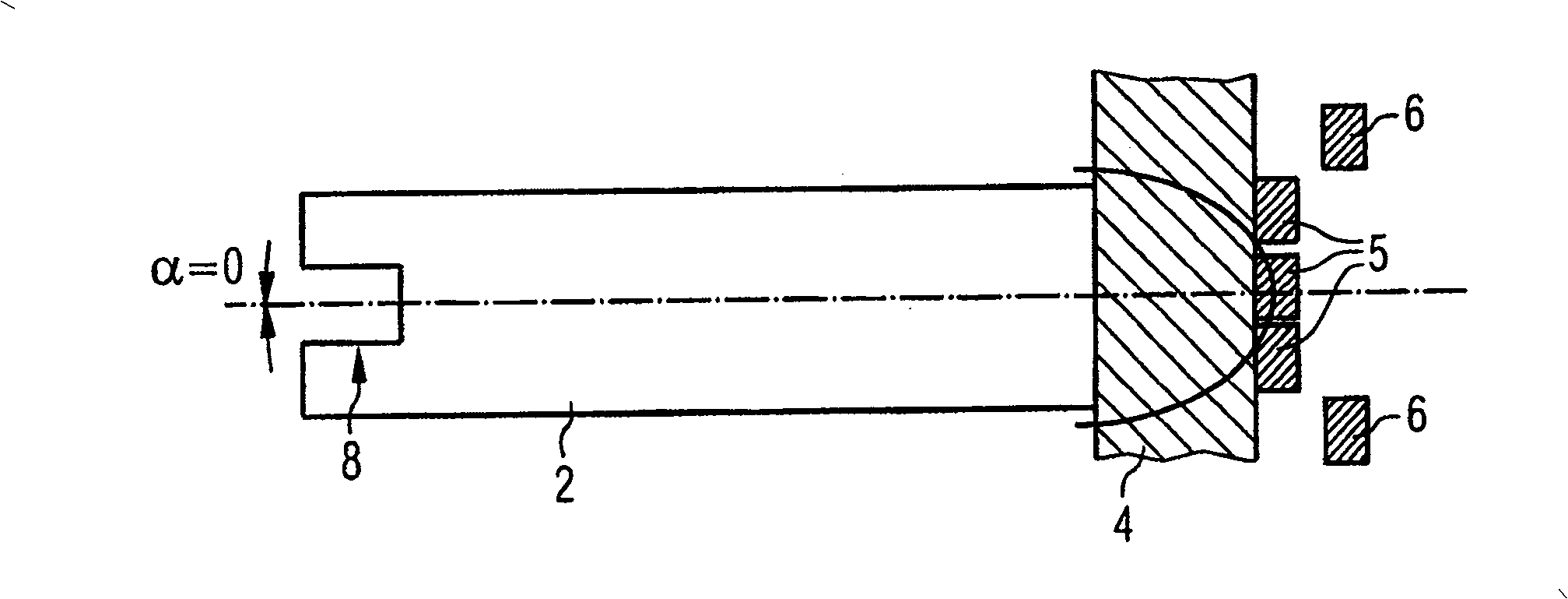
In a magnetically passive position sensor, a mechanical axis (11) and a magnetic axis (12) of a magnet (2) point toward the same contact spring element from two or more contact spring elements (5, 6). This results, in particular, in the end regions of the position sensor achieving a particularly high accuracy. The magnet (2) has a guide polygon (8) which is used to hold the magnet (2) in a holder (10) such that it cannot rotate.

Description

technical field [0001] The present invention relates to a passive magnetic position sensor having a magnet arranged on a pivot arm and having a plurality of contact spring elements arranged within the pivot range of the magnet, the contact spring elements being located opposite a thick film mesh, and the The contact spring element can be moved towards the thick film mesh by means of a magnet. Furthermore, the invention relates to a method for mounting a passive magnetic position sensor in which the magnets are mounted such that they can pivot over a contact spring element on the side opposite the thick film mesh. Background technique [0002] Passive magnetic position sensors are widely used together with level sensors in modern motor vehicle fuel tanks and are known from DE 19648539 A1. The magnet is cylindrical and is held in a hole in the pivot arm. One end of the magnet is located opposite the at least one contact spring element. When the pivot arm and magnet are move...

Claims


Application Information

Patent Timeline
Patent Type & Authority Patents(China)
IPC IPC(8): G01B7/00G01D5/14G01D5/165G01F23/38
CPCG01F23/38G01D5/165G01D5/1655Y10T29/49002
Inventor B·波尔
Owner CONTINENTAL AUTOMOTIVE GMBH
Learn More