Apparatus for storage of potential energy

A technology of equipment and potential energy, applied in the field of equipment for storing potential energy, which can solve the problems that the equipment is not very effective, and the buoy cannot generate enough force.

Inactive Publication Date: 2008-07-16
兰尼・扎卡里亚・多尔 +2
View PDF6 Cites 3 Cited by
  • Summary
  • Abstract
  • Description
  • Claims
  • Application Information

AI Technical Summary

Problems solved by technology

This known device has the disadvantage that the buoy does not generate enough force to push the piston down, or at least to a stroke large enough to allow water to enter the column
Therefore, this device is not very effective

Method used


Image

  • Apparatus for storage of potential energy
  • Apparatus for storage of potential energy
  • Apparatus for storage of potential energy

Examples


Embodiment Construction

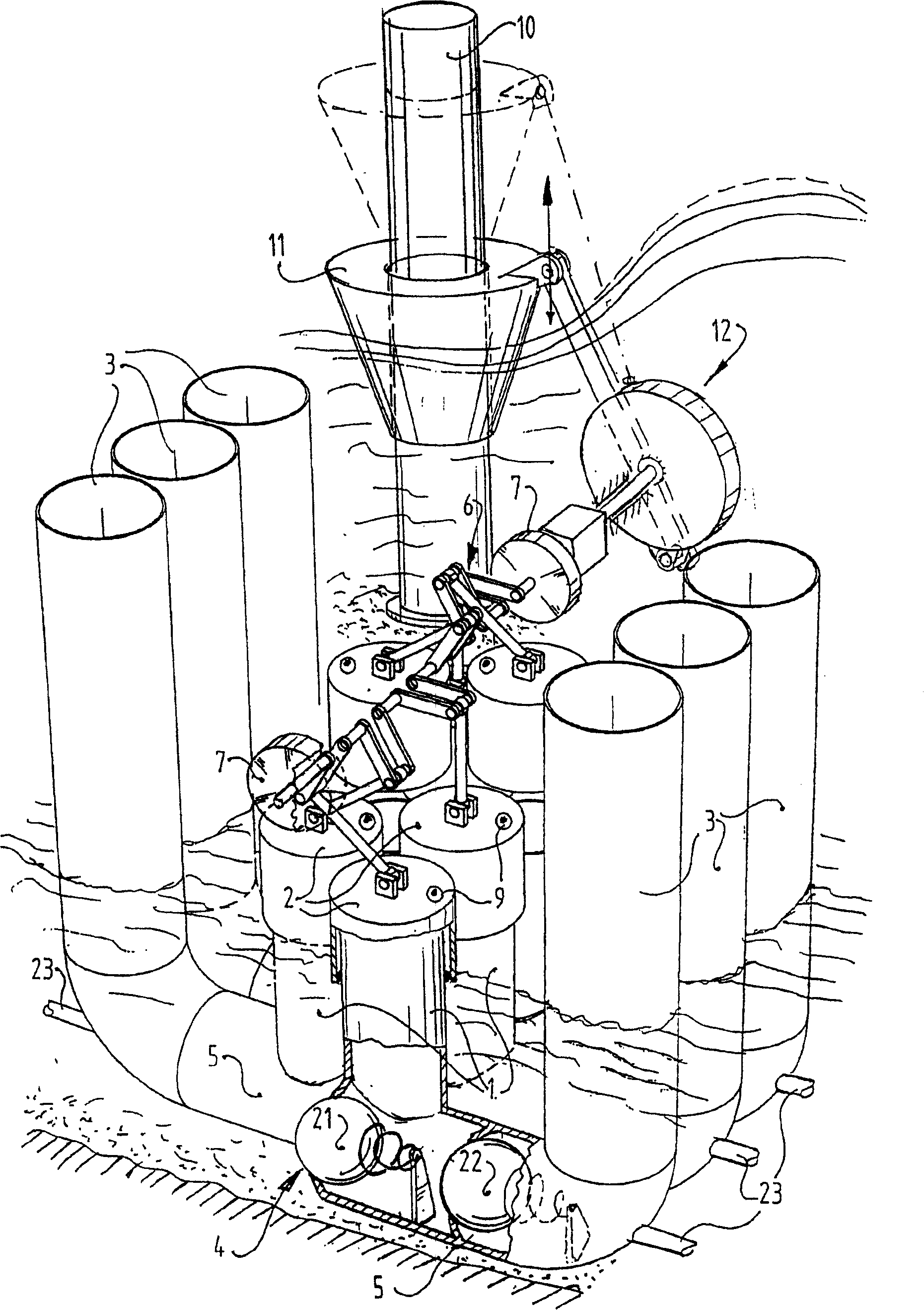
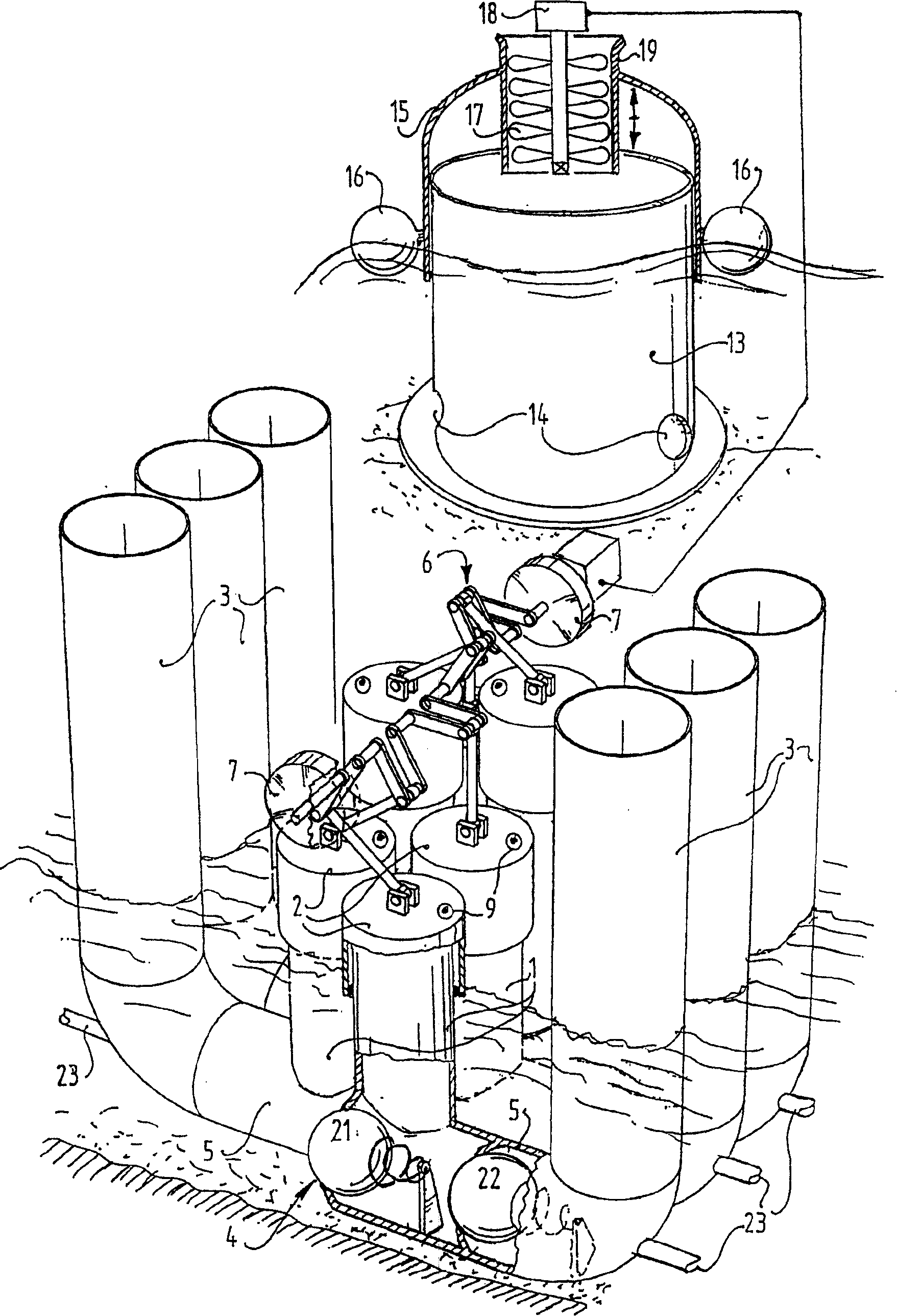
[0014] exist figure 1 , a first embodiment of an apparatus for storing potential energy using water in a deep body of water, such as the sea, is shown. This device includes one or more modules 20 . exist Figure 1-3 In the preferred embodiment, the apparatus has six modules 20 arranged in a symmetrical configuration. However, other configurations and more or less than six modules are possible.

[0015] Each module 20 comprises a cylinder 1, a piston 2 slidably connected to this cylinder 1, a post 3 for storing seawater entering through an inlet 4 connected to the cylinder / piston 1 and 2 are connected, and the connecting pipe 5 connects the cylinder 1 and the column 3 to each other. Thus, the device comprises a crankshaft 6 connected to the piston 2 of the module 20 and two flywheels 7 mounted on the crankshaft 6 for reciprocating the piston 2 relative to the cylinder 1 . In this first embodiment, a windmill 8 is provided, which is electrically or mechanically coupled to t...


PUM


Abstract

An apparatus for storage of potential energy using water from a deep body of water is described. The apparatus comprises one module including a cylinder, a piston slidably connected to the cylinder, a column for storing the water from the deep body of water received through an inlet being in communication with the cylinder / piston, and a connecting tube which mutually connects the cylinder and the column. The apparatus further comprises driving means for reciprocally displacing the piston in relation to the cylinder, wherein the driving means is a crankshaft drivingly connected to the piston and at least one flywheel mounted to the crankshaft for counteracting the pressure as result of the water stored in the column.

Description

technical field [0001] The present invention relates to a device for storing potential energy using water in a deep body of water, comprising a module comprising a cylinder, a piston slidably connected to the cylinder, a A column for storing water in the middle, the water enters through an inlet that communicates with the cylinder block / piston, and also includes a connecting pipe that communicates the cylinder block and the column with each other, wherein the device also includes a driving device for reciprocating the piston relative to the cylinder . Background technique [0002] Such a device is known from British Patent Publication No. 2068469. The drive of this known device consists of a buoy fixed to the piston for the reciprocation of the piston. The buoy moves freely up and down in the waves for which this device is applicable. A disadvantage of this known device is that the buoy does not generate enough force to push the piston down, or at least down a stroke larg...

Claims


Application Information

Patent Timeline
Patent Type & Authority Patents(China)
IPC IPC(8): F03B13/14F03B13/18F03D9/02F03B13/16F03B13/24F03D9/00
CPCY02E10/38F03B13/187F03D9/001F03B13/24F03D9/025F03B13/147Y02E60/17Y02E60/16Y02E10/72F03B13/1815F03D9/14F03D9/12F03D9/28F03D9/25Y02E10/30Y02P80/10Y02E70/30F03B13/14
Inventor 扎卡里亚·卡里尔·多尔
Owner 兰尼・扎卡里亚・多尔
Why Eureka
Try Eureka