Developer storing container and connecting member

A technology for connecting parts and developing agents, which is applied in the fields of instruments, electrography, optics, etc., and can solve problems such as toner ingress, fitting looseness, and insufficient transmission of driving force

Inactive Publication Date: 2008-06-25
SHARP KK
View PDF8 Cites 0 Cited by
  • Summary
  • Abstract
  • Description
  • Claims
  • Application Information

AI Technical Summary

Problems solved by technology

Therefore, in order to absorb the assembly dimensional error of these parts, it is necessary to leave a margin in size when manufacturing each part for easy assembly, resulting in loose fitting of each part after assembly.
Therefore, the driving force for rotating the stirring blades 101a, 101c cannot be sufficiently transmitted to the toner container 101, causing a problem that the toner enters the gap between the bearings 101e, 101f, 101g and the shaft and solidifies.

Method used


Image

  • Developer storing container and connecting member
  • Developer storing container and connecting member
  • Developer storing container and connecting member

Examples


Embodiment Construction

[0022] Below, refer to Figure 1- Figure 4 One embodiment of the present invention will be described.

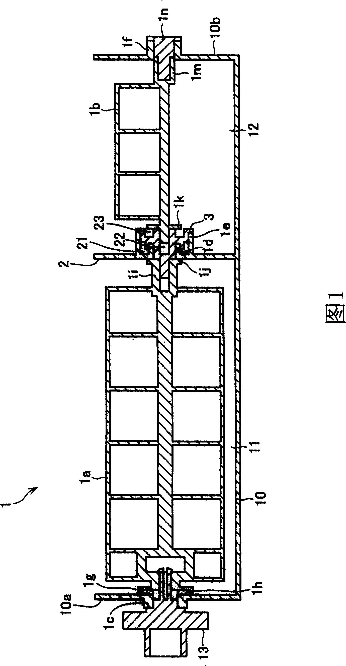
[0023] FIG. 1 shows the structure of a toner cartridge (developer storage container) 1 according to this embodiment. This figure is a cross-sectional view along the rotation axis of the photoreceptor.

[0024] The toner cartridge 1 has a toner storage portion (developer storage portion) 11 and a waste toner storage portion (waste developer storage portion) 12 . The toner storage portion 11 and the waste toner storage portion 12 are formed by isolating the case 10 of the toner cartridge 1 with a partition wall (fixed wall) 2 and are adjacent to each other in the direction of the rotation axis described later. The partition wall 2 is integrally formed with the housing 10 of the toner cartridge 1 and fixed to the housing 10 . A stirring blade (developer stirring blade) 1 a is provided in the toner storage portion 11 . The stirring blade 1 a is constituted by a planar grid-s...


PUM


Abstract

In a developer-storing container of the present invention, an agitation blade used in a toner-storing section and an agitation blade used in a waste-toner-storing section are coupled by a rotor. The rotor is interdigitated to a bearing mounted on a partition wall. The partition wall is made to be a fixed wall so that precision of interdigitation of the agitation blade of the toner-storing section, the rotor, and the agitation blade of the waste-toner-storing section is improved. Consequently, a developer-storing container that is easy to assemble and in which precision of interdigitation is high is realized.

Description

technical field [0001] The present invention relates to a developer storage container for agitating and storing a developer supplied to a developing tank of an image forming apparatus. Background technique [0002] Image forming apparatuses such as copiers are often provided with a developer storage container for supplying developer to a developing tank. For example, in Japanese Patent Laid-Open Publication No. 2001-356577 (published on December 26, 2001), the following powder storage container is described: the stirring member is arranged on the upper end of the container from the one with a larger opening area. The opening can be inserted and withdrawn, and the stirring member can be easily attached to the container main body, and the stirring member can be easily taken out from the container main body when reused. [0003] In addition, Japanese Patent Laid-Open Publication No. 2003-337465 (published on November 28, 2003) describes a toner cartridge that is detachably mou...

Claims


Application Information

Patent Timeline
Patent Type & Authority Patents(China)
IPC IPC(8): G03G15/08G03G21/12
CPCG03G21/1676G03G2221/1657G03G21/16G03G15/0896G03G21/1647G03G2221/163
Inventor 真田义明国广久志见原幸一
Owner SHARP KK
Why Eureka
Try Eureka