
Liquid crystal aberration correcting element

An aberration correction, liquid crystal technology, applied in optics, beam sources, instruments, etc., can solve the problems of large aberration, difficult to obtain phase difference, no complete aberration correction, etc., to achieve the effect of correcting deformation and improving accuracy

Inactive Publication Date: 2008-06-11
BINIT
View PDF11 Cites 0 Cited by
  • Summary
  • Abstract
  • Description
  • Claims
  • Application Information

AI Technical Summary

Problems solved by technology

[0011] In addition, as another problem, when using the liquid crystal aberration correction element to apply the opposite phase wave as mentioned above, if the generated aberration is large, it may be difficult to obtain a phase difference that only offsets the aberration.
As a result, there is a problem that the aberrations are not completely corrected

Method used


Image

  • Liquid crystal aberration correcting element
  • Liquid crystal aberration correcting element
  • Liquid crystal aberration correcting element

Examples


Embodiment Construction

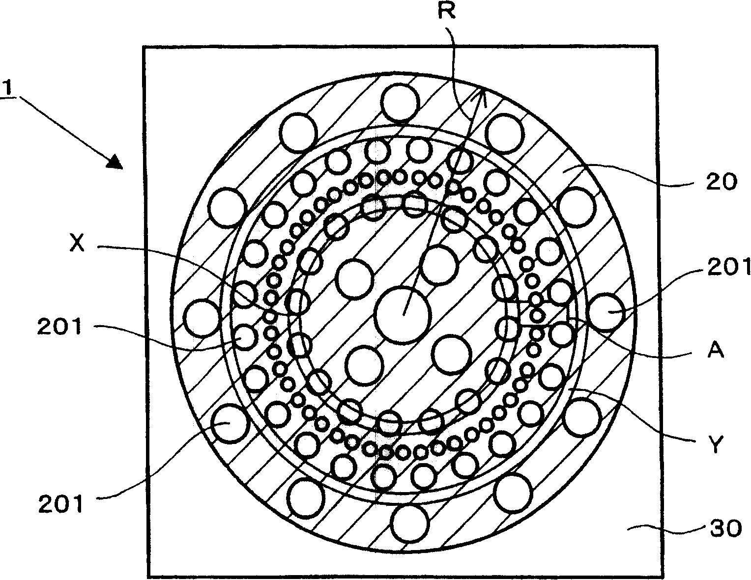
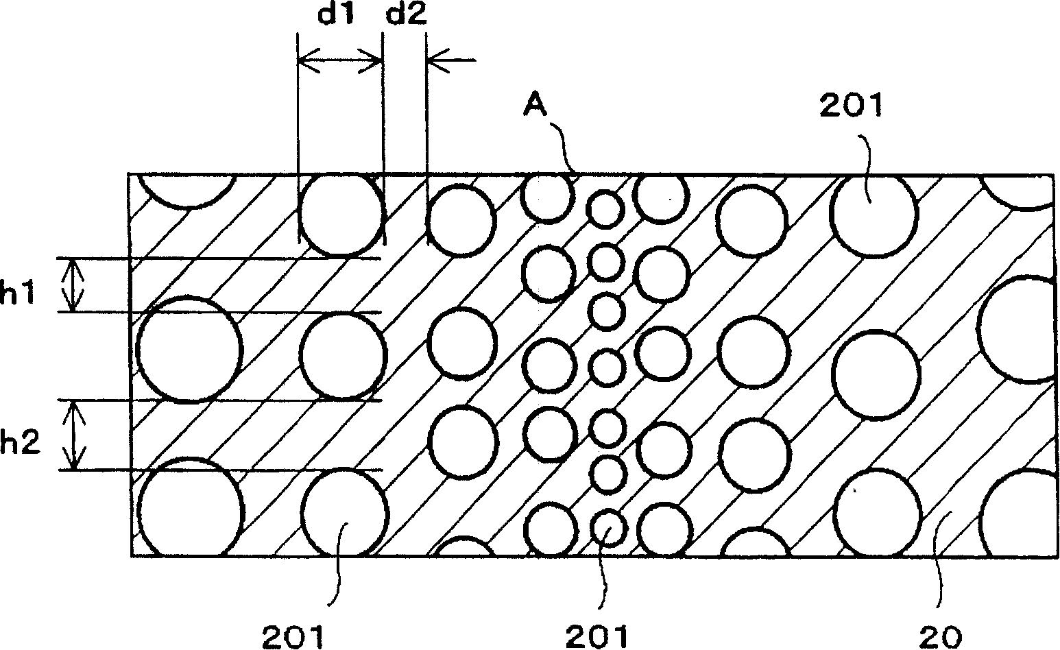
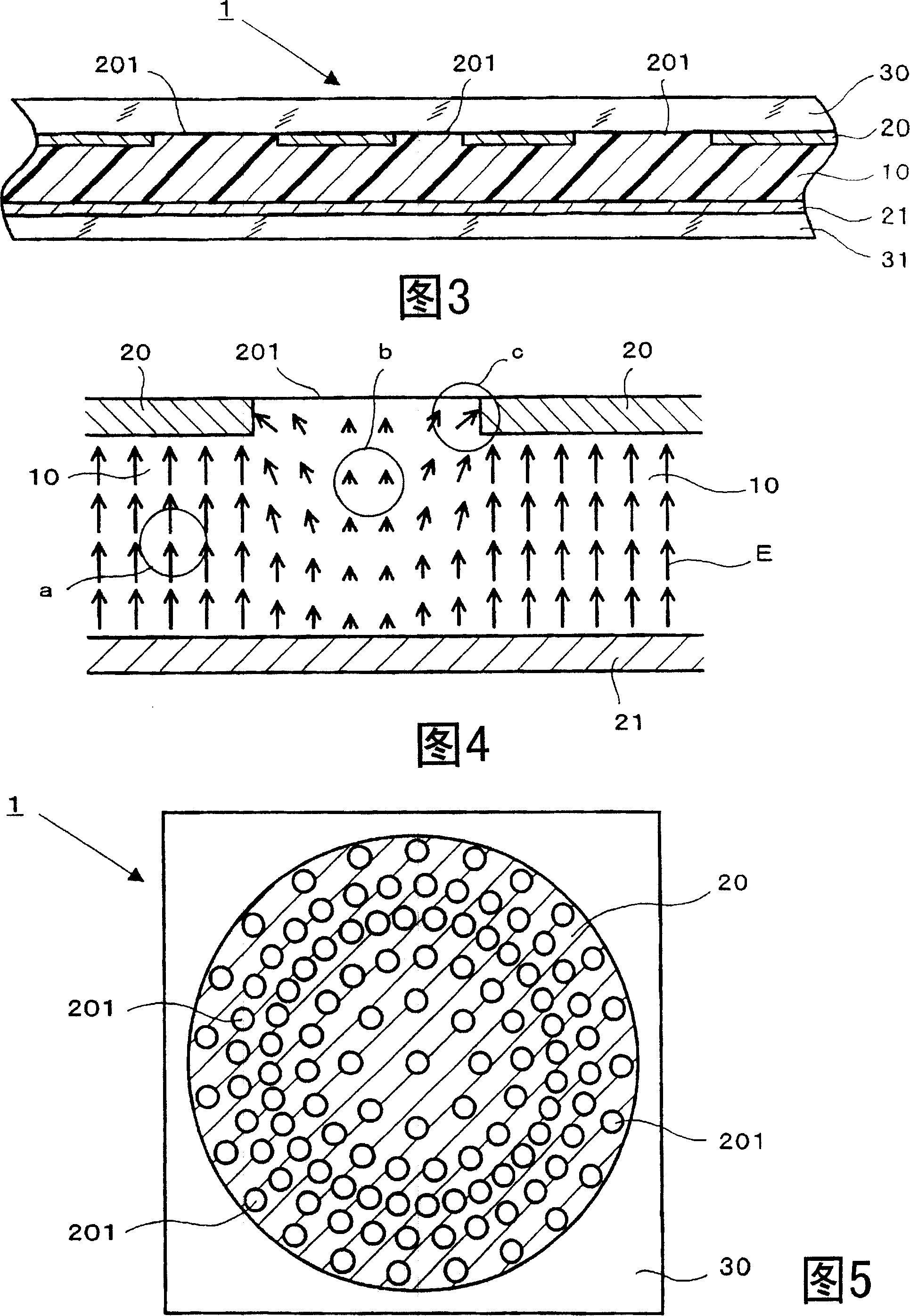
[0044] The present invention provides a liquid crystal aberration correction element having a structure including a liquid crystal and a plurality of electrodes facing each other across the liquid crystal, and a plurality of non-electrode portions where no electrode material is present are formed on at least one of the electrodes On the inside of the non-electrode part, the liquid crystal is not uniformly oriented when a voltage is applied, the shape of the non-electrode part is circular, and the diameter and arrangement interval of a plurality of non-electrode parts are divided into concentric circles along the electrode Change in the radial direction during the shape (first invention).

[0045] According to this structure, at the center of a plurality of non-electrode parts, the opposite electrode forms a weak electric field in the vertical direction, and at the end parts of the non-electrode parts, an electric field is formed in an oblique direction, so the electric field is di...


PUM


Abstract

A novel liquid crystal aberration correcting element capable of correcting aberration caused by the thickness deviation, etc. of an optical disk to thereby enhance a recording / reproducing accuracy. The liquid crystal aberration correcting element comprises liquid crystal and a plurality of electrodes facing each other across liquid crystal. A plurality of non-electrode portions (201) each free from an electrode material and in a hole shape are formed in an electrode (20), and a lens effect occurs on the inner side of a non-electrode portion (201) due to non-uniform orientation of liquid crystal when a voltage is applied. The plurality of non-electrode portions (201) are changed in size or locating interval or the both according to their positions on an electrode (20) to thereby linearly correct aberration.

Description

Technical field [0001] The present invention relates to the technical field of a liquid crystal aberration correction element for correcting aberrations generated during recording / reproduction by an optical pickup in an optical disc device. Background technique [0002] Conventionally, various optical discs such as CDs and DVDs have been known as information recording media. These optical discs have aberrations (deformation of the focal point) due to thickness deviation or bending caused by rotation, and therefore, it is required to correct the aberrations to improve the accuracy of recording / reproduction. [0003] Especially recently, BD (Blu-ray Disc) has attracted attention as a next-generation optical disc. The standard is to increase the wavelength of the light source from 650nm to 405nm, increase the numerical aperture (NA) of the objective lens from 0.6 to 0.85, and increase the surface recording density to about 5 times that of conventional DVDs. Here, the spherical aberr...

Claims


Application Information

Patent Timeline
Patent Type & Authority Patents(China)
IPC IPC(8): G02F1/13G11B7/135G11B7/125G02F1/1343G11B7/1392
CPCG02F2203/18G11B7/13927G02F1/134309G02F1/153
Inventor 中川信义前山裕行佐藤进
Owner BINIT
Learn More