
Site-specific traffic analysis including identification of a traffic path

a traffic path and site-specific technology, applied in the direction of measurement devices, railway signalling and safety, instruments, etc., can solve the problems of inability to distinguish the traffic lane on which the detected object is located, the induction loop only allows the detection of a sufficiently large metallic object, and the inconvenient installation of wire loops in the roadway. achieve the effect of reliable and more accurate traffic analysis

Active Publication Date: 2018-05-22
ROBERT BOSCH GMBH
View PDF22 Cites 0 Cited by
  • Summary
  • Abstract
  • Description
  • Claims
  • Application Information

AI Technical Summary

Benefits of technology

[0010]It is an object of the present invention to create a device for site-specific traffic analysis, which allows a more reliable and more accurate traffic analysis than known systems.
[0013]A particularly simple installation of the device results from the device being configured to identify the location of a traffic path. In this way, the location of a traffic path may be automatically identified, without requiring an exact orientation or positioning of the radar sensor with respect to the traffic space to be monitored. By assigning the detected objects to a thus identified traffic path, objects belonging to the same traffic path may be evaluated more accurately as a result of the assignment. For example, objects moving outside a traffic path may be excluded for the evaluation of the traffic on the traffic path. By assigning the particular detected objects to the particular traffic path, a traffic analysis which is related to the traffic path is thus made possible. For example, if the locations of multiple traffic lanes are ascertained, a traffic analysis separated according to traffic lanes may be carried out. It is thus not necessary to predefine the number of traffic lanes. Rather, the individual traffic lanes may be detected based on the detected object movements.

Problems solved by technology

However, the necessary installation of the wire loop in the roadway is complex.
Moreover, an induction loop only allows the detection of a sufficiently large metallic object.
If a light barrier extends across a roadway having multiple traffic lanes, a distinction regarding on which traffic lane a detected object is situated is not readily possible.

Method used


Image

  • Site-specific traffic analysis including identification of a traffic path
  • Site-specific traffic analysis including identification of a traffic path
  • Site-specific traffic analysis including identification of a traffic path

Examples


Embodiment Construction

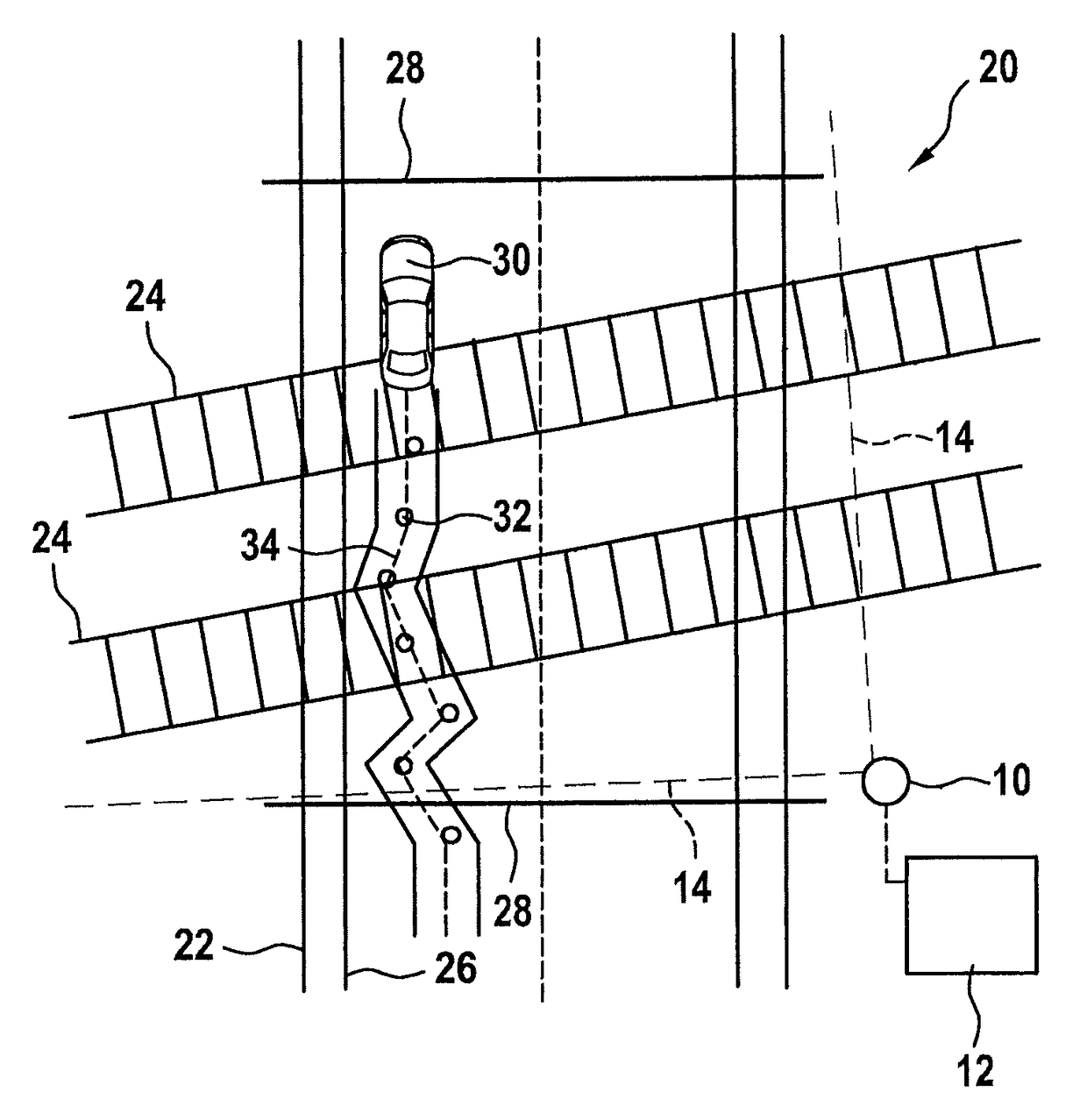
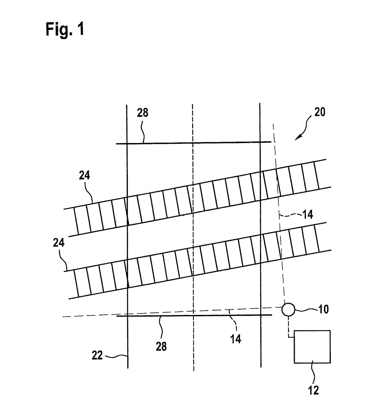
[0023]FIG. 1 shows a schematic illustration of a radar sensor 10 and of an evaluation unit 12 connected to radar sensor 10 or integrated therein. Radar sensor 10 is an FMCW radar sensor having a transceiver device, which includes a patch antenna array and has a schematically illustrated field of vision 14, which includes an azimuth angle range of at least 90°. Multiple antenna elements are situated horizontally offset from each other. Field of vision 14 preferably includes an azimuth angle range of at least 160°.

[0024]Radar sensor 10 is situated at the edge of a traffic space 20, which is captured by field of vision 14.

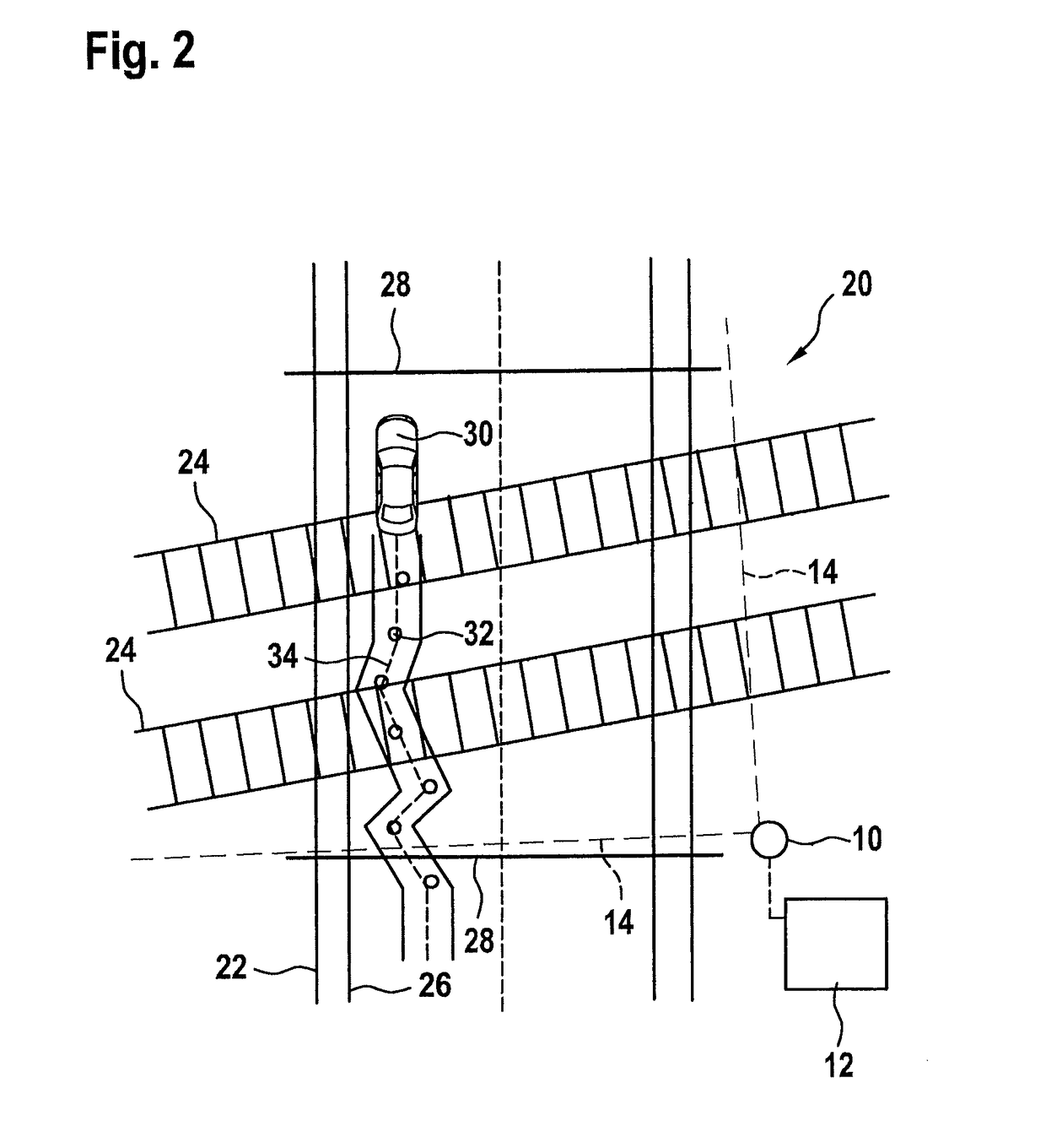
[0025]Traffic space 20 includes a road 22 and may include a railroad having tracks 24 and / or a footpath 26 (FIG. 2), for example.

[0026]FIG. 1 additionally schematically shows barriers 28 of a railroad crossing.

[0027]FIG. 2 shows, by way of example, a situation with an object 30 in the form of a vehicle detected by radar sensor 10. Evaluation unit 12 receives data on o...


PUM


Abstract

A device for site-specific traffic analysis includes: a radar sensor at a traffic space; and an evaluation unit configured to (i) ascertain object trajectories from chronological sequences of object positions of respective objects detected by the radar sensor and moving in the traffic space, (ii) identify the location of at least one traffic path based on a concentration of object trajectories, and (iii) assign further detected objects to a respective traffic path whose location has been identified.

Description

BACKGROUND OF THE INVENTION[0001]1. Field of the Invention[0002]The present invention relates to a device for site-specific traffic analysis, including an arrangement of at least one radar sensor at a traffic space and including an evaluation unit.[0003]2. Description of the Related Art[0004]Induction loops (also referred to as contact loops) which are embedded into the roadway are known for the detection of vehicles in a traffic lane in front of traffic lights, which allow the presence of the vehicle to be detected by a change in the inductivity due to a vehicle situated over the induction loop. However, the necessary installation of the wire loop in the roadway is complex. Moreover, an induction loop only allows the detection of a sufficiently large metallic object.[0005]In addition, light barrier measuring devices are known, in which a light barrier is oriented transversely to the roadway. A vehicle passing through the light barrier is thus detectable. A transmitter must be situa...

Claims


Application Information

Patent Timeline
Patent Type & Authority Patents(United States)
IPC IPC(8): G08G1/01B61L23/04G08G1/052G01S13/06B61L29/30
CPCG08G1/0133B61L23/041B61L29/30G08G1/052G08G1/0116G08G1/0145G01S13/06
Inventor LEHNERTZ, BENEDIKT
Owner ROBERT BOSCH GMBH
Learn More