
Switch device

a technology of switch and switch body, which is applied in the direction of electric devices, legends, roads, etc., can solve the problems of poor operation feel and difficulty in enhancing waterproofness, and achieve the effect of excellent operability and waterproofness

Active Publication Date: 2018-05-01
KK TOKAI RIKA DENKI SEISAKUSHO
View PDF9 Cites 2 Cited by
  • Summary
  • Abstract
  • Description
  • Claims
  • Application Information

AI Technical Summary

Benefits of technology

The invention is a switch device that can be operated by a single knob through switching and tilt operation. The device provides good operability and is waterproof.

Problems solved by technology

According to the switch device of Patent Document 1, the switch contacts used to select an electric mirror and adjust the mirror surface angle of the electric mirror are of the sliding contact type, resulting in a problematic poor operational feel due to the effects of sliding resistance.
Thus, it is difficult to make the circuit board waterproof due to the structure of the circuit board, resulting in difficulty in enhancing waterproofness.

Method used


Image

  • Switch device
  • Switch device
  • Switch device

Examples


first embodiment

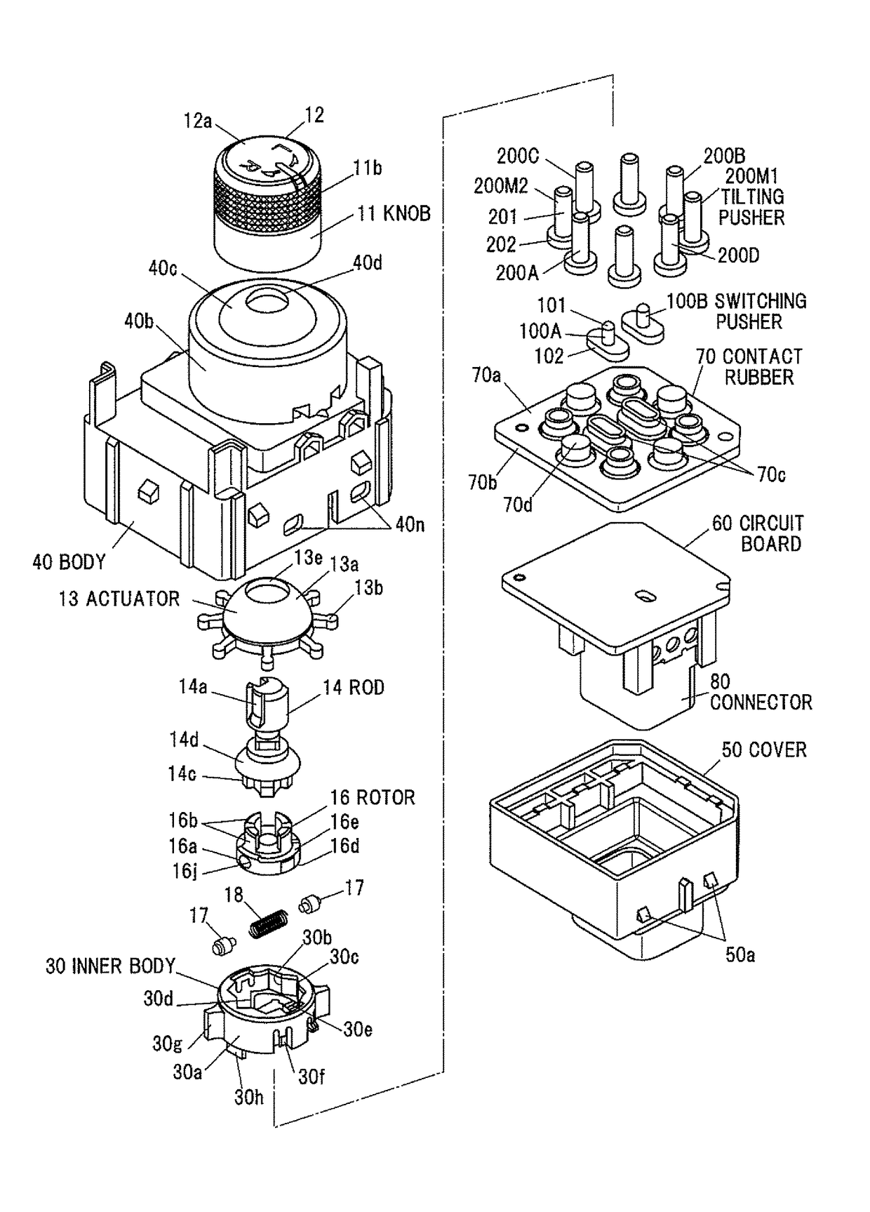
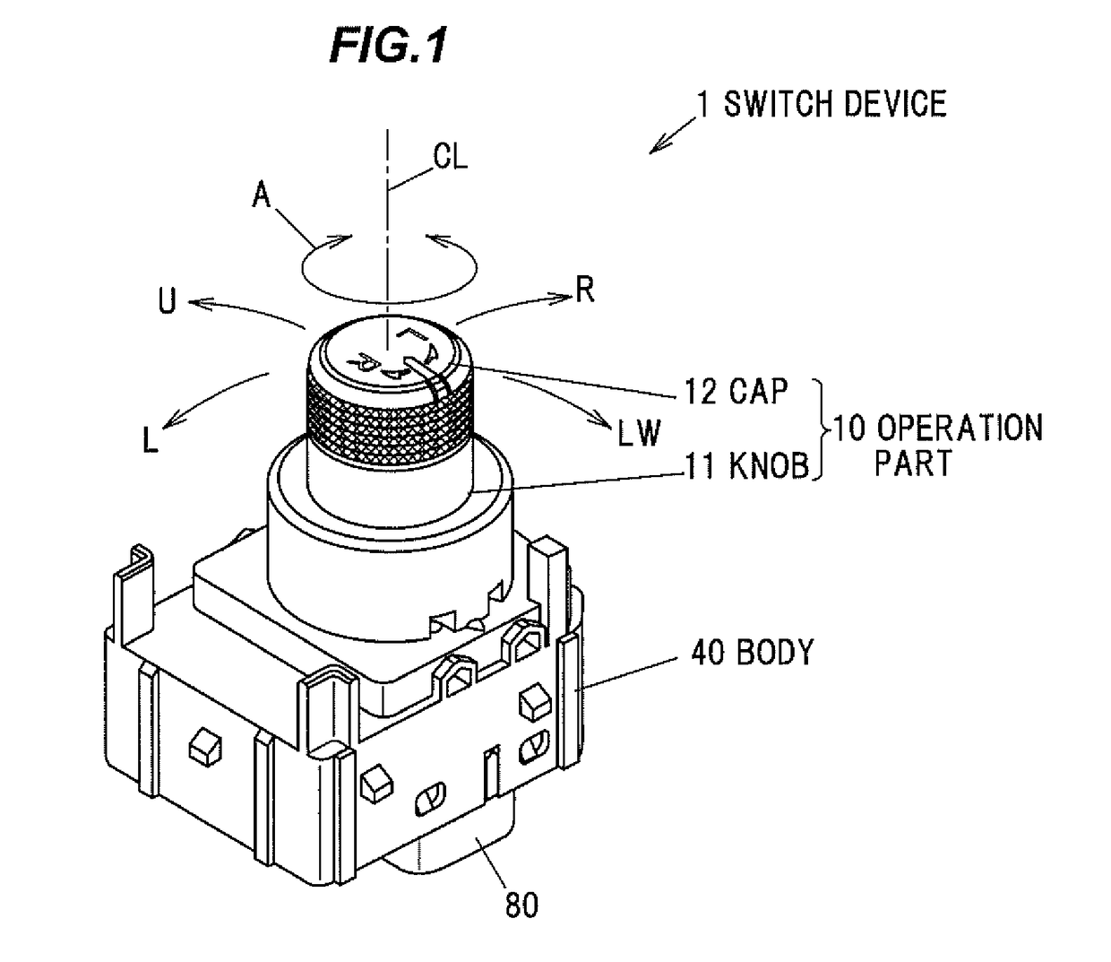
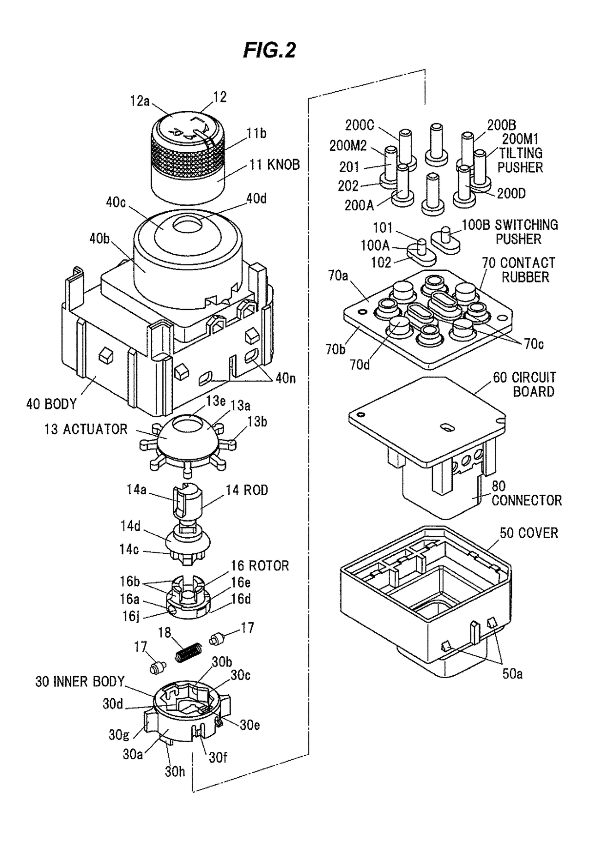
[0027]FIG. 1 is an overall perspective view of a switch device according to a first embodiment of the present invention. FIG. 2 is an exploded perspective view of the switch device according to the first embodiment of the present invention. Further, FIG. 3 is a longitudinal cross-sectional view of the switch device, including an operational axis CL, according to the first embodiment of the present invention. A switch device 1 according to the first embodiment of the present invention includes a first push mechanism that, by a rotation operation of an operation part 10, selects and activates a first push switch part; a second push mechanism that, by a tilt operation of the operation part 10, activates a second push switch part; a circuit board 60 having the first push switch part and the second push switch part mounted thereto; and a contact rubber 70 that is interposed between the circuit board 60 and switching pushers 100 as well as tilting pushers 200 includes contacts correspondi...

second embodiment

[0098]FIG. 6 is an overall perspective view of a switch device according to a second embodiment of the present invention. FIG. 7 is an exploded perspective view of the switch device according to the second embodiment of the present invention. Further, FIG. 8 is a longitudinal cross-sectional view of the switch device, including the operational axis CL, according to the second embodiment of the present invention. A switch device 1001 according to the second embodiment of the present invention includes a first push mechanism that, by a rotation operation of an operation part 1010, selects and activates a first push switch part; a second push mechanism that, by a tilt operation of the operation part 1010, activates a second push switch part; the circuit board 60 having the first push switch part and the second push switch part mounted thereto; and a contact rubber 1070 that is interposed between the circuit board 60 and switching pushers 1100 as well as tilting pushers 1200 includes co...


PUM


Abstract

A switch device includes an operation part, a first push mechanism that, by a rotation operation of the operation part, selects and activates a first push switch part, a second push mechanism that, by a tilt operation of the operation part, activates a second push switch part, a circuit board including the first push switch part and the second push switch part mounted thereto, and a contact rubber interposed between the circuit board and the first and second push mechanisms. The contact rubber includes contacts corresponding to the first push switch part and the second push switch part and is configured such that the contacts contact with or separate from the corresponding switch parts by a movement of the first push mechanism and the second push mechanism. The contact rubber is formed so as to cover an entire upper surface of the circuit board.

Description

[0001]The present application is based on Japanese patent application No. 2015-113065 filed on Jun. 3, 2015, the entire contents of which are incorporated herein by reference.BACKGROUND OF THE INVENTION[0002]1. Field of the Invention[0003]The present invention relates to a switch device.[0004]2. Description of the Related Art[0005]Switch devices for controlling vehicle mirrors are known that can be used for selecting an electric mirror and adjusting a mirror surface angle of the electric mirror through the use of a single operation knob (refer to Patent Document 1, for example). Such a switch device can be used for selecting an electric mirror on the right side or the left side by a rotation operation of the operation knob and switching a switch circuit provided on the front surface of a circuit board in four ways by a tilt operation of the operation knob in a crisscross direction from a neutral position (refer to Patent Document 1, for example).[0006]For example, in this switch dev...

Claims


Application Information

Patent Timeline
Patent Type & Authority Patents(United States)
IPC IPC(8): H01H9/00H01H25/04H01H9/04
CPCH01H25/04H01H9/04H01H25/041H01H2300/012H01H2219/036H01H2231/026H01H2237/006H01H2025/043H01H2025/046
Inventor HISADA, MASAHITOKOBAYASHI
Owner KK TOKAI RIKA DENKI SEISAKUSHO
Learn More