Controlling wheel hop in a vehicle axle

a technology of vehicle axle and control system, which is applied in the direction of vehicle position/course/altitude control, instruments, braking systems, etc., can solve the problems that the condition of wheel hop can be particularly damaging to the rear axle components, and achieve the effect of reducing engine torqu

Active Publication Date: 2018-02-27
FORD GLOBAL TECH LLC
View PDF23 Cites 0 Cited by
  • Summary
  • Abstract
  • Description
  • Claims
  • Application Information

AI Technical Summary

Benefits of technology

[0006]A method for controlling wheel hop at a vehicle axle includes pulsing pressure in the wheel brakes of the axle, if one of a difference between average front and rear wheel speeds exceeds a reference difference, a frequency of a signal produced by an accelerometer mounted on the axle exceeds a reference frequency, and a frequency of a lock ring torque exceeds a second reference frequency; and reducing engine torque.

Problems solved by technology

Because of the high torques generated at each axle shaft and the high frequency of the loading, the wheel hop condition can be particularly damaging to rear axle components, especially if the axle differential is locked, and the vehicle is turning causing a torque bias across the locked differential.

Method used


Image

  • Controlling wheel hop in a vehicle axle
  • Controlling wheel hop in a vehicle axle
  • Controlling wheel hop in a vehicle axle

Examples


Embodiment Construction

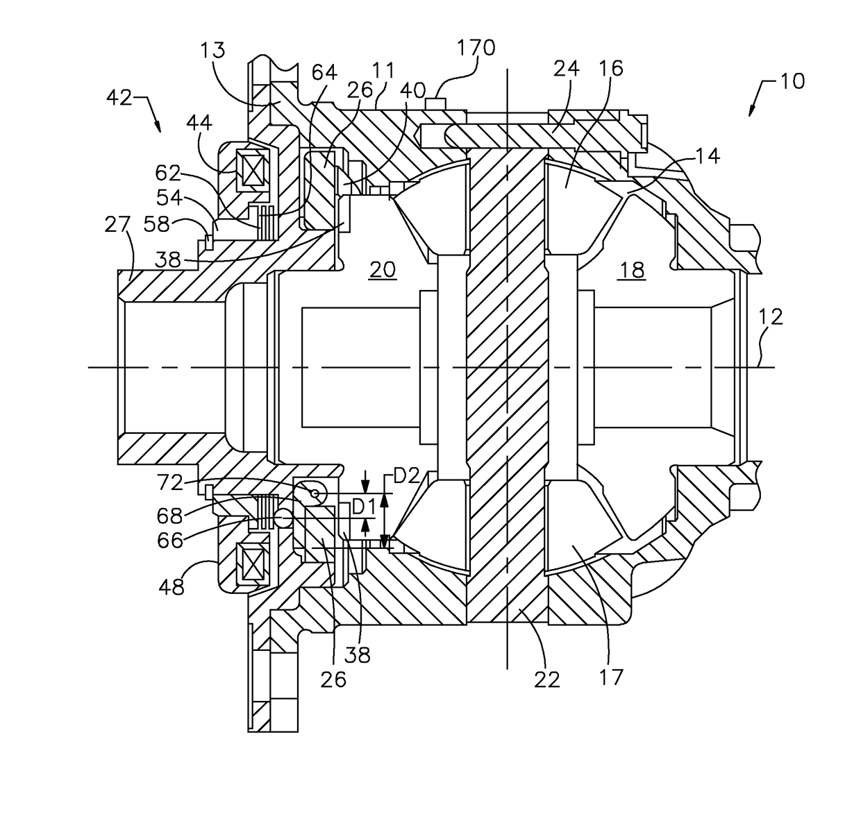
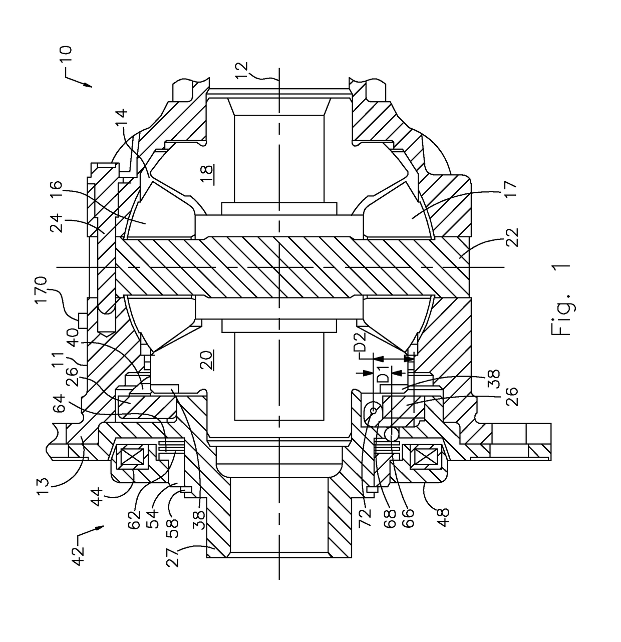
[0018]FIG. 1 shows a differential mechanism 10, which includes a differential case 11, preferably of cast iron or steel, supported on a stationary housing (not shown) for rotation about a lateral axis 12. The case 11 is driveably connected through a bevel ring gear (not shown) to the output of a transmission or transfer case. The ring gear, secured to the case 11 at the attachment bolt holes on a flange 13, is supported for rotation about axis 12.

[0019]The case 11 encloses an internal chamber 14, which contains bevel pinions 16, 17. Chamber 14 contains a right-side bevel gear 18 meshing with the pinions 16, 17, driveably connected to an output shaft, which is secured by a spline to side gear 18 and extends laterally at the right-hand side from the case 11 to a driven wheel of a motor vehicle. Chamber 14 contains a left-side bevel gear 20 meshing with the pinions 16, 17, driveably connected to a second output shaft, which is secured by a spline to side gear 20 and extends laterally f...


PUM


Abstract

A method for controlling wheel hop at a vehicle axle includes determining that one of a difference between average front and rear wheel speeds exceeds a reference difference, a frequency of a signal produced by an accelerometer mounted on the axle exceeds a reference frequency, and a frequency of a lock ring torque exceeds a second reference frequency; pulsing pressure in the wheel brakes of the axle; and reducing engine torque.

Description

BACKGROUND OF THE INVENTION[0001]1. Field of the Invention[0002]This invention relates generally to a vehicle driveline, and particularity to using engine and brake control to prevent damage to structural components during wheel hop conditions.[0003]2. Description of the Prior Art[0004]During certain vehicle maneuvers, which involve a particular combination of rear wheel speed, rear wheel torque, tire and road surface conditions, and suspension parameters, the rear solid beam axle can resonate causing a situation known as wheel hop.[0005]Because of the high torques generated at each axle shaft and the high frequency of the loading, the wheel hop condition can be particularly damaging to rear axle components, especially if the axle differential is locked, and the vehicle is turning causing a torque bias across the locked differential.SUMMARY OF THE INVENTION[0006]A method for controlling wheel hop at a vehicle axle includes pulsing pressure in the wheel brakes of the axle, if one of ...

Claims


Application Information

Patent Timeline
Patent Type & Authority Patents(United States)
IPC IPC(8): B60T7/12B60T8/175
CPCB60T8/175B60T2201/14
Inventor ANDONIAN, BRIAN J.POVIRK, JACOB M.ROBERTSON, DAVID A.GUO, JIHONGMELOCHE, PATRICKPIETRZYK, GARY M.
Owner FORD GLOBAL TECH LLC
Why Eureka
Try Eureka