
Solar panel array

a solar panel and array technology, applied in the field of solar energy collection, can solve the problems of reducing the requirement of physical space, preserving significant real estate, and supporting the use of real estate for solar cell coverage, etc.

Active Publication Date: 2018-01-30
KALMAN ANDREW E
View PDF17 Cites 5 Cited by
  • Summary
  • Abstract
  • Description
  • Claims
  • Application Information

AI Technical Summary

Benefits of technology

[0010]The present inventor realized in an inventive moment that if, at the point of deployment, multiple solar panels hosting multiple solar cells could be caused to be electrically interconnected in a parallel manner through mechanical connectors, significant real estate might be preserved. The inventor therefore constructed a unique solar panel array for solar vehicles or other solar apparatus that supported more use of real estate for solar cell coverage by eliminating or sharply reducing the requirement of physical interconnection through the use of wiring or cabling between solar cells and between individual solar panels in an array. A significant optimization of available real estate for solar cell coverage results, with no impediment to efficiency of power delivery created.

Problems solved by technology

The problem stated above is that optimum use of real estate is desirable for a solar panel array such as might be connected to a spacecraft such as a satellite or a space vehicle such as a rover for example.

Method used


Image

  • Solar panel array
  • Solar panel array
  • Solar panel array

Examples


Embodiment Construction

[0024]The inventors provide a unique solar panel array that can be furled and unfurled in a fanfold fashion using unique hinge assemblies and which communication of power from the array to a connected host panel can be accomplished through printed circuit board traces and special accommodations made possible through the hinge assemblies. The present invention will be described in enabling detail using the following examples, which may describe more than one relevant embodiment falling within the scope of the present invention.

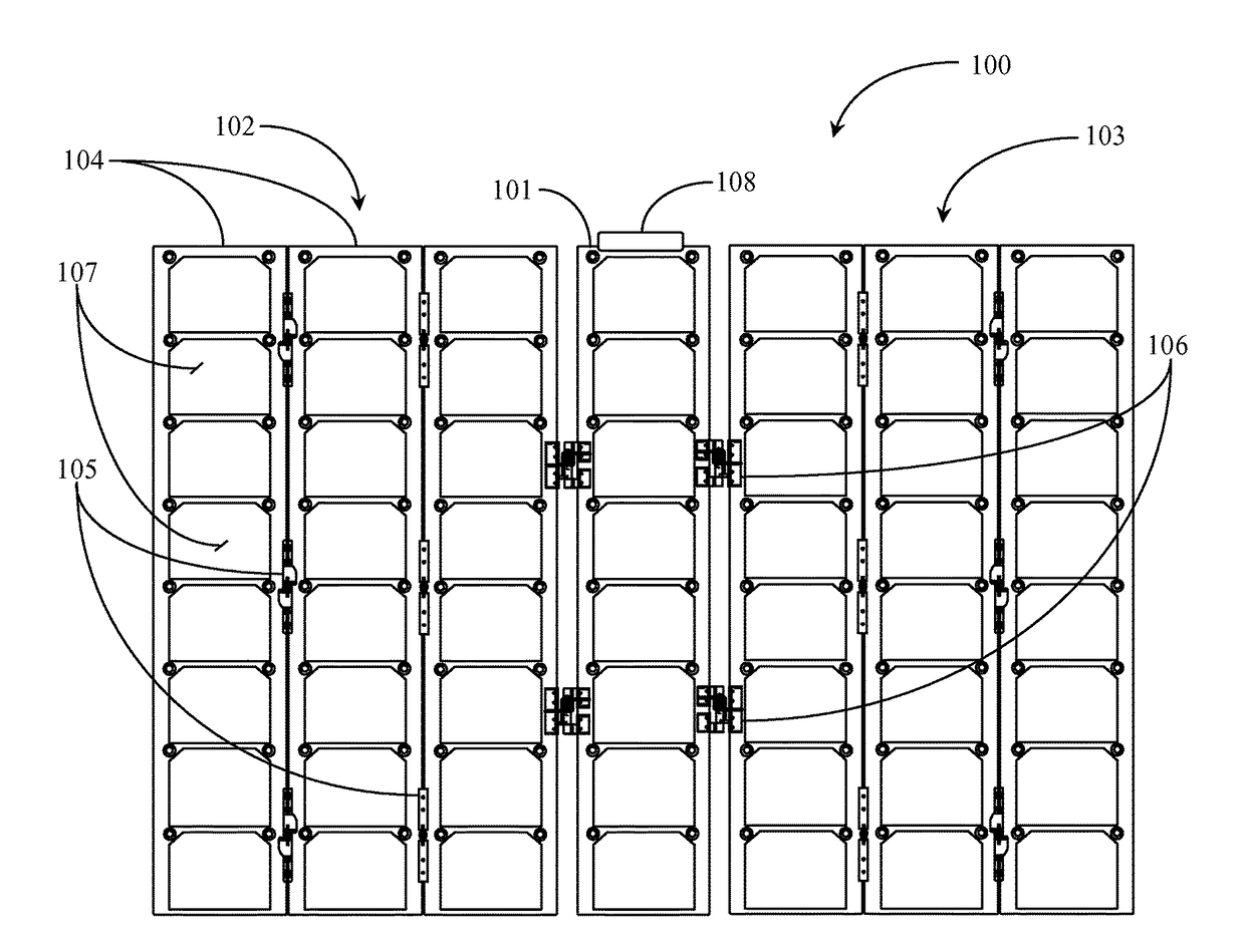
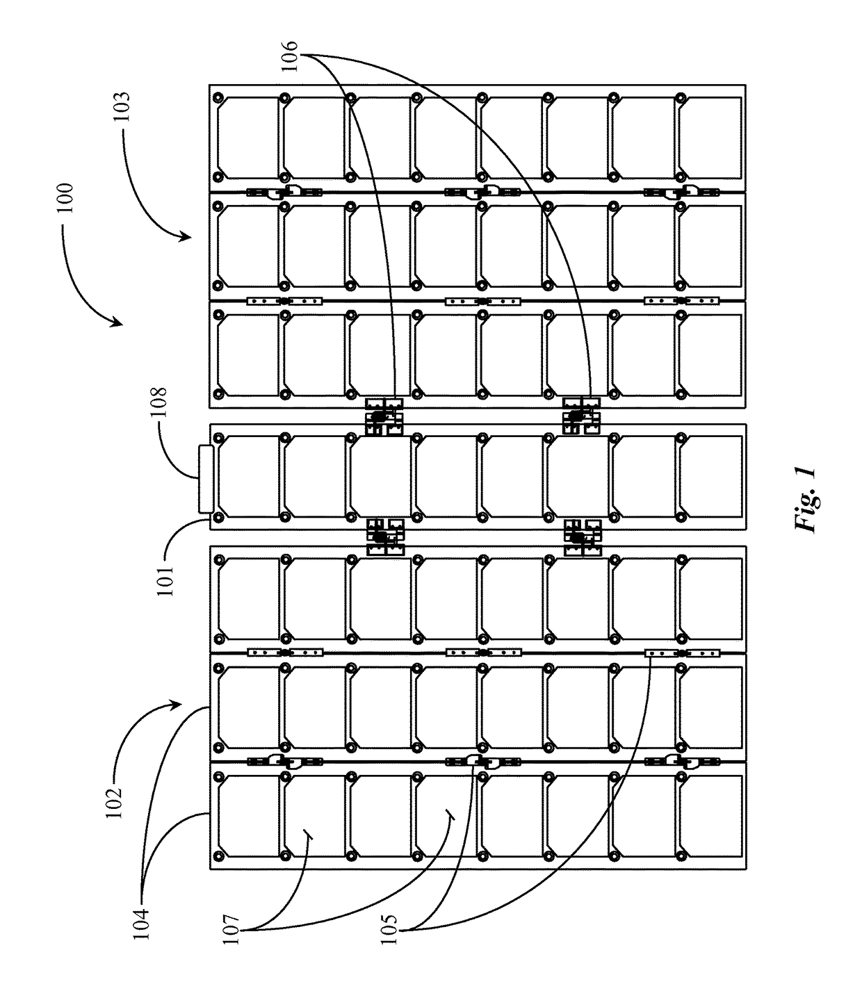
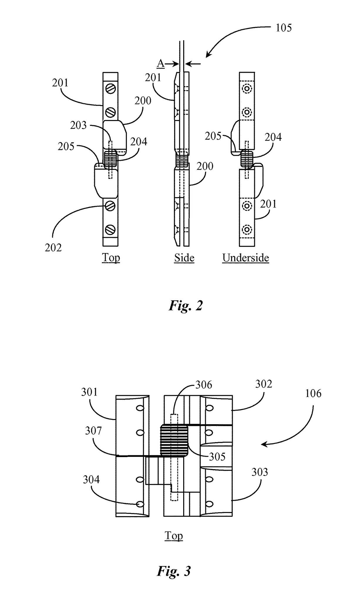
[0025]FIG. 1 is an elevation view of a solar panel array 100 folded out to 180 degrees. Solar panel array 100 includes a host solar panel 101 comprising an elongate printed circuit board (PCB) with a number of individual solar cells 107 mounted thereon and electrically connected in series for power transfer purposes. Host panel 101 has two fanfold style solar panel winglets or wings 102 and 103 connected thereto 5 using offset hinge assemblies 106. Each fanfold...


PUM

PropertyMeasurementUnit
thicknessaaaaaaaaaa
thickaaaaaaaaaa
thicknessaaaaaaaaaa

Abstract

A solar panel array includes a number of elongate printed circuit boards (PCBs), each PCB supporting a number of individual solar cells linearly mounted thereon and electrically connected in series to form a solar panel, and a number of hinge assemblies, each hinge assembly including two or more hinge bodies, two backing plates, one spring, and one hinge pin, the hinge assemblies mounted between adjacent solar panels using conventional hardware in a manner connecting them together such that they may be folded over one another in a fanfold arrangement or deployed out to one hundred and eighty degrees.

Description

CROSS-REFERENCE TO RELATED DOCUMENTS[0001]The present invention claims priority to a U.S. provisional patent application Ser. No. 61 / 368,901, filed Jul. 29, 2010, disclosure of which is incorporated herein in their entirety herein by reference.BACKGROUND OF THE INVENTION[0002]1. Field of the Invention[0003]The present invention is in the field of solar energy collection and pertains particularly to methods and apparatus for electrically interconnecting solar cells and panels deployed in a solar panel array.[0004]2. Discussion of the State of the Art[0005]In the art of solar power generation, multiple solar cells are often mounted on a substrate to form a solar panel capable of high efficiency generation of solar energy (electricity). Nearly all spacecraft including solar-powered vehicles have solar cells to gather energy from the Sun. Typically speaking, solar cells used in such implementations have an efficiency rating of greater than twenty-eight percent. In most implementations, ...

Claims


Application Information

Patent Timeline
Patent Type & Authority Patents(United States)
IPC IPC(8): H01R43/00H02S40/34H02S40/36H01R35/04H02S30/20
CPCH01R35/04H02S30/20H02S40/36H02S40/34Y10T29/49117H01R2201/26Y02E10/50
Inventor KALMAN, ANDREW E.
Owner KALMAN ANDREW E
Learn More