
Adaptive control of motor vehicle powertrain

a technology of motor vehicles and powertrains, applied in electrical control, propulsion using engine-driven generators, driver input parameters, etc., can solve problems such as difficulty, subsequent vehicle launch, and driver disconcerting the driver, and consequent change in engine response may occur

Active Publication Date: 2017-12-26
JAGUAR LAND ROVER LTD
View PDF16 Cites 0 Cited by
  • Summary
  • Abstract
  • Description
  • Claims
  • Application Information

AI Technical Summary

Benefits of technology

[0049]Aspects of the present invention thus provide for a progressive change of filter map over the period for which one of said filters provides a relative delay, so that the driver experiences a progressive change between source and target propulsion request filters rather than a step change.
[0069]According to another aspect of the present invention for which protection is sought there is provided an electronic control system for defining the output of a vehicle propulsion source in relation to the position of an accelerator pedal by reference to a plurality of torque maps held within a memory, said system being adapted to detect a first operating mode of the vehicle and apply a source map, to detect a second operating mode and select a target map, to apply a filter to the source map and target map so as to more or less delay the effect of a propulsion request and to blend from the source map to the filtered target map.

Problems solved by technology

This is because high engine drag upon release of the accelerator pedal may cause one or more wheels of the vehicle to sink into the sand, making subsequent vehicle launch more difficult.
However difficulties may arise if the operating mode is automatically selected in response to a vehicle sensing a change of operating condition.
The consequent change in engine response may be disconcerting to the driver, especially if such automatic mode changes are repeated frequently.
This change may be disconcerting, and it would be desirable to indicate to the driver that such a change is in progress; visual or audible indicators are not considered desirable because the driver may be overloaded with information, and not immediately appreciate what the indicator is indicating.
Furthermore automatic mode changes may occur frequently, and such indicators may be a distraction.

Method used


Image

  • Adaptive control of motor vehicle powertrain
  • Adaptive control of motor vehicle powertrain
  • Adaptive control of motor vehicle powertrain

Examples


Embodiment Construction

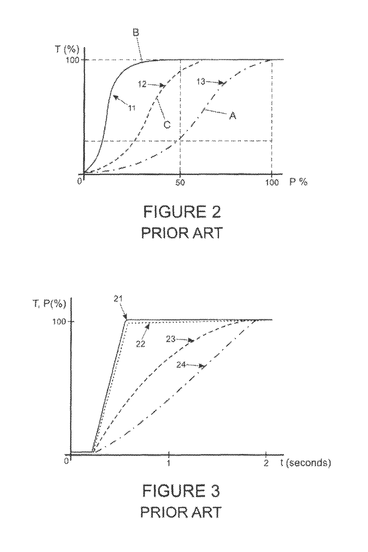
[0084]FIG. 2 illustrates pedal progression maps of different vehicle operating modes, and demonstrates how in some modes a greater accelerator pedal movement is required in order to achieve a given engine output torque T.

[0085]FIG. 3 illustrates for different vehicle operating modes, the filtered response of an advancing accelerator pedal position, and demonstrates how a target torque of FIG. 2 may be reached more or less quickly.

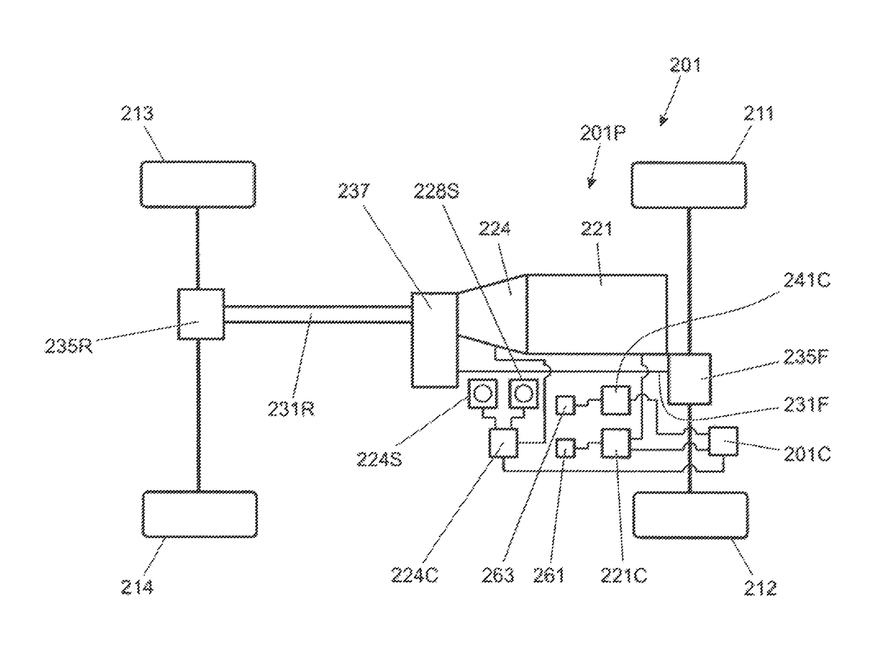
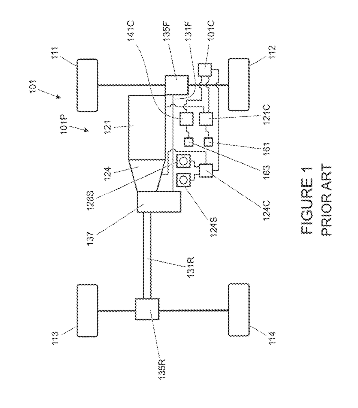
[0086]FIG. 4 is a schematic illustration of a motor vehicle 201 according to an embodiment of the present invention. Like features of the vehicle 201 of FIG. 4 to those of the vehicle 101 of FIG. 1 are shown with like reference numerals prefixed numeral 2 instead of numeral 1. Thus engine 121 of the vehicle 101 of FIG. 1 corresponds to engine 221 of the vehicle 201 of FIG. 4.

[0087]The vehicle 201 has a VCU 201C programmed with accelerator pedal progression maps that are used to determine engine torque T as a function of accelerator pedal position P. In the ...


PUM


Abstract

Embodiments of the present invention provide a vehicle having different operating modes, and for each such mode a different characteristic of output torque and accelerator pedal position. The rise of output torque in response to a propulsion request is more or less delayed according to the instant operating mode. The invention provides for blending of the response to a propulsion request so that the delay is progressively varied between a source and target operating mode.

Description

FIELD OF THE INVENTION[0001]Embodiments of the present invention relate to adaptive control of a powertrain of a motor vehicle. In particular, embodiments of the present invention relate to adaptive control of a source of motive power, for example an internal combustion engine and in particular, but not exclusively, to the response of the engine to an operator command in consequence of a change of engine operating mode. The change of engine operating mode may in turn be related to a change of operating mode of a vehicle in which the engine is installed, for example an operating mode related to the terrain under a vehicle. Aspects of the invention relate to a system, to a method and to a vehicle.BACKGROUND[0002]Internal combustion engines of vehicles may have operating modes which may be selectable by the driver. Thus in some vehicles an economy mode, a normal mode and a sport mode may be provided, each mode having a different engine response to one or more commands of the driver. Ty...

Claims


Application Information

Patent Timeline
Patent Type & Authority Patents(United States)
IPC IPC(8): B60W50/10F02D11/10B60W50/12F02D41/02F02D41/24B60K26/04B60W50/00F02D41/14B60L50/16
CPCB60W50/10B60W50/12F02D11/10F02D11/105F02D41/021F02D41/2422B60K26/04F02D2200/702B60W2050/0014B60W2050/0026B60W2050/0042B60W2050/0052B60W2540/10B60W2540/106B60W2710/0605B60W2710/0666F02D2041/1422F02D2041/1432B60W10/04B60W10/06B60W2510/0657B60W2510/0661B60W2540/215
Inventor DARNELL, PAULHEMES, ELLIOTROBERTS, MARK
Owner JAGUAR LAND ROVER LTD
Learn More