
Communication module assembly

a technology of communication module and assembly, which is applied in the direction of electrical equipment, connection, coupling device connection, etc., can solve the problems of increasing production costs, requiring relative space, and limited position of connecting ports, so as to minimize the space required for connecting and disconnecting operations of cables, minimize the overall device, and minimize the effect of operation tim

Active Publication Date: 2017-10-17
SOLID
View PDF24 Cites 2 Cited by
  • Summary
  • Abstract
  • Description
  • Claims
  • Application Information

AI Technical Summary

Benefits of technology

The present invention allows for a smaller overall device size by connecting communication modules in a plug-in type to minimize the space needed for cable connecting and disconnecting operations. Additionally, it reduces the time required for these operations because they do not require any additional steps.

Problems solved by technology

When the cables are used in this way, since there is a basic need for an operation space for fastening and disconnecting the cables, relatively much space is required.
Furthermore, since there is a need to be able to connect the cables after mounting the communication module, the position of the connecting port is also limited only to the front or the side that allows the check.
In addition to spatial limitations as described above, in order to mount and dismount the communication module in the production process, since it is necessary to assemble and disassemble the plurality of cables, it takes a lot of time, which leads to a problem of an increase in production costs.
However, in order to implement such a guide structure, since an additional space is required for the module and the housing, and in some cases, another structure needs to be added, there is a difficulty to be implemented in a device of a limited size.

Method used


Image

  • Communication module assembly
  • Communication module assembly
  • Communication module assembly

Examples


Embodiment Construction

[0021]Exemplary embodiments of the present invention will be described below in more detail with reference to the accompanying drawings. The present invention may, however, be embodied in different forms and should not be construed as limited to the embodiments set forth herein. Rather, these embodiments are provided so that this disclosure will be thorough and complete, and will fully convey the scope of the present invention to those skilled in the art. Throughout the disclosure, like reference numerals refer to like parts throughout the various figures and embodiments of the present invention.

[0022]The present invention may make various changes and may have a plurality of embodiments, and specific embodiments will now be illustrated in the drawings and described in detail in the detailed description. However, this is not intended to limit the present invention for a particular embodiment, and it should be understood to include all changes, equivalents and alternations which fall ...


PUM


Abstract

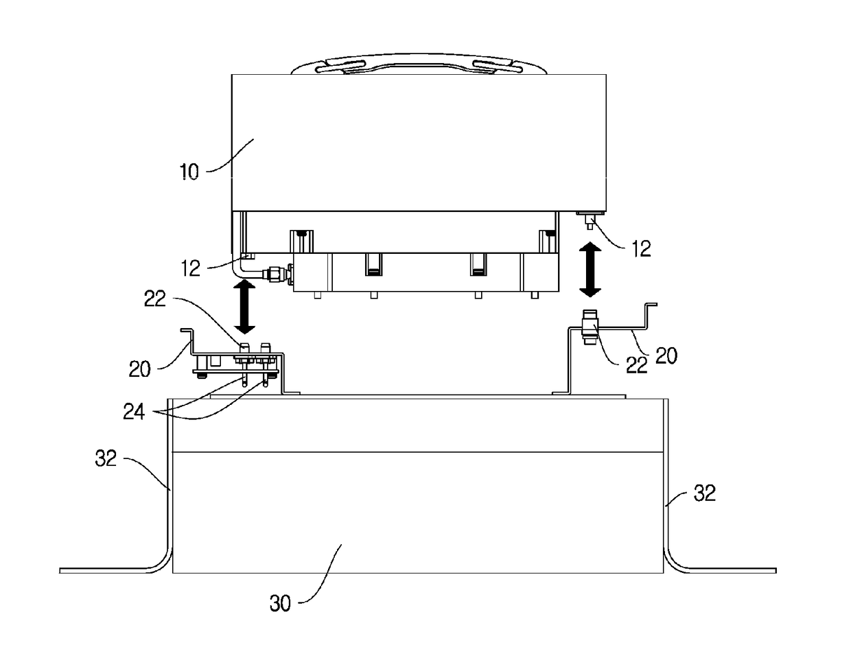
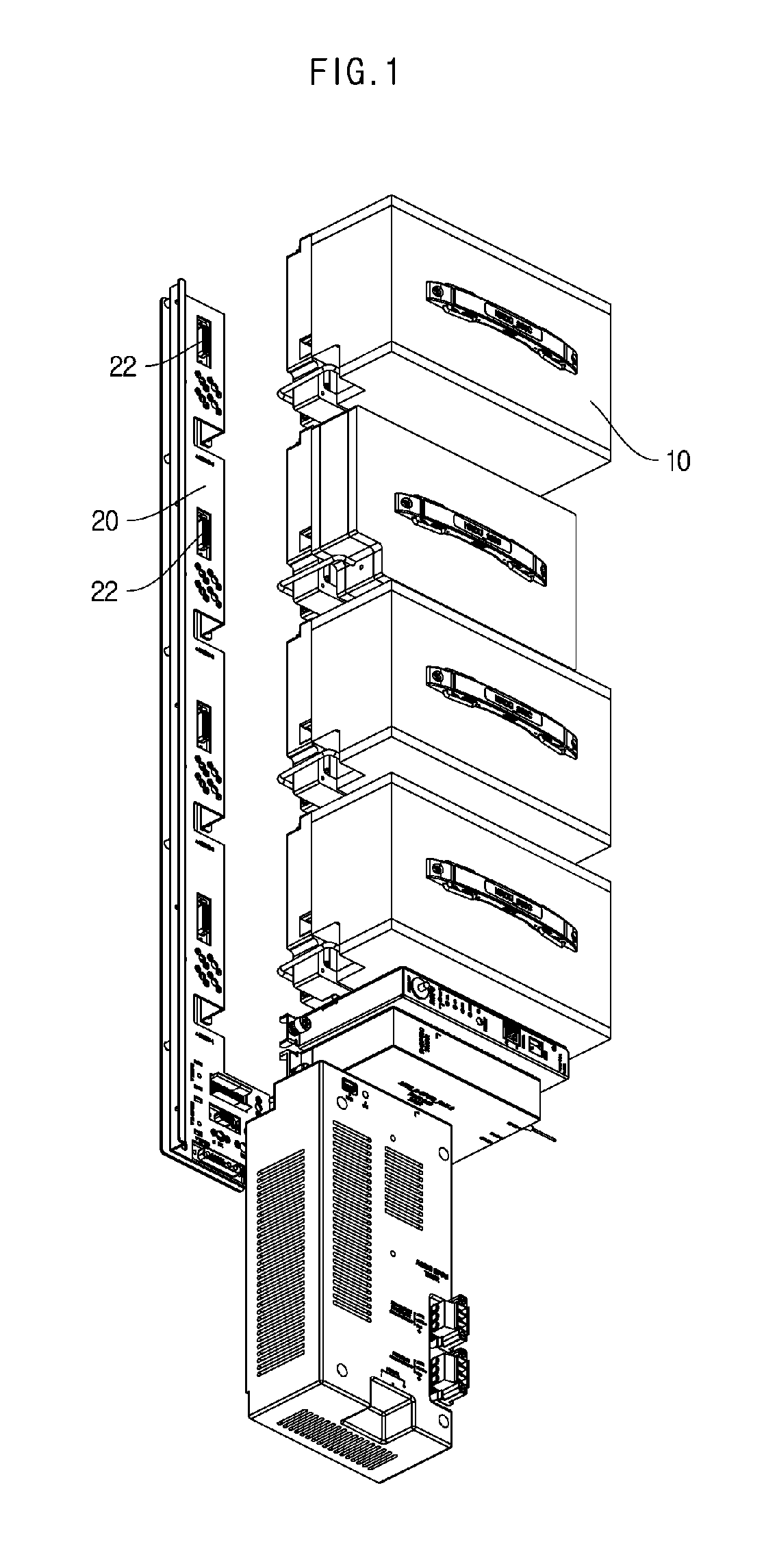
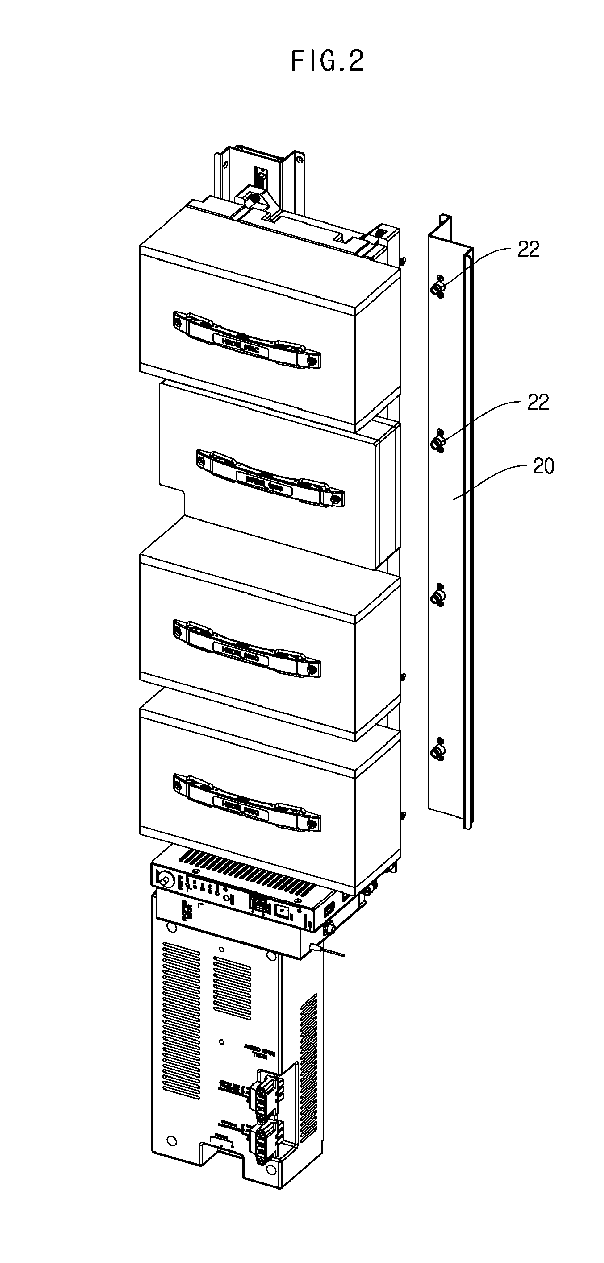
The present invention relates to a communication module assembly. The present invention is a communication module assembly which is electrically connected to a communication device and is supplied with power and signal, and can include a connection port unit that is supplied with the power and the signal from the communication device; a cable connection portion which is provided in the connection port unit, and to which cables electrically connected to the communication device is connected; a plurality of communication modules that is stacked on and connected to the connection port unit in a plug-in type; and a guide means for guiding the communication module such that the communication modules are connected to the connection port unit in a central direction.

Description

TECHNICAL FIELD[0001]The present invention relates to a communication module assembly, and more particularly, to a communication module assembly that is capable of miniaturizing an overall device, by implementing a configuration in which communication modules are connected to connection ports in a plug-in type to minimize a space required for connecting and disconnecting operations of cables.BACKGROUND ART[0002]In general, inside the communication devices, a plurality of cables is used to connect power and signal between several mounted communication modules. When the cables are used in this way, since there is a basic need for an operation space for fastening and disconnecting the cables, relatively much space is required. Furthermore, since there is a need to be able to connect the cables after mounting the communication module, the position of the connecting port is also limited only to the front or the side that allows the check.[0003]In addition to spatial limitations as descri...

Claims


Application Information

Patent Timeline
Patent Type & Authority Patents(United States)
IPC IPC(8): H01R13/631H04Q1/02H01R25/16H01R9/26
CPCH01R13/631H01R25/16H04Q1/02H01R9/26H04Q1/06
Inventor LEE, DONG WONWON, SO YEON
Owner SOLID
Learn More