Stroller frame
a frame and stroller technology, applied in the field of strollers, can solve the problems of inconvenience in storage and transportation, inconvenience in use, and complicated structure of the conventional stroller, and achieve the effect of small siz
- Summary
- Abstract
- Description
- Claims
- Application Information
AI Technical Summary
Benefits of technology
Problems solved by technology
Method used
Image
Examples
first embodiment
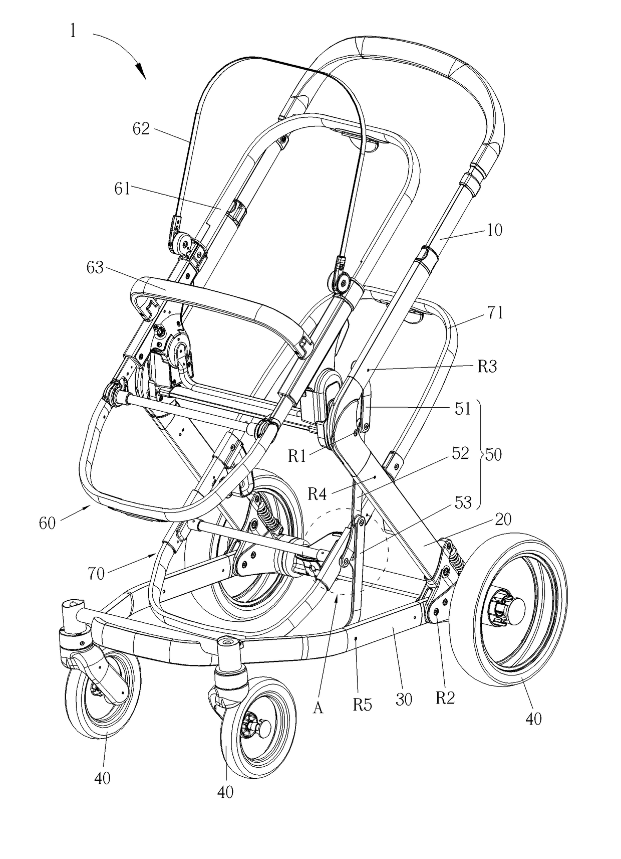
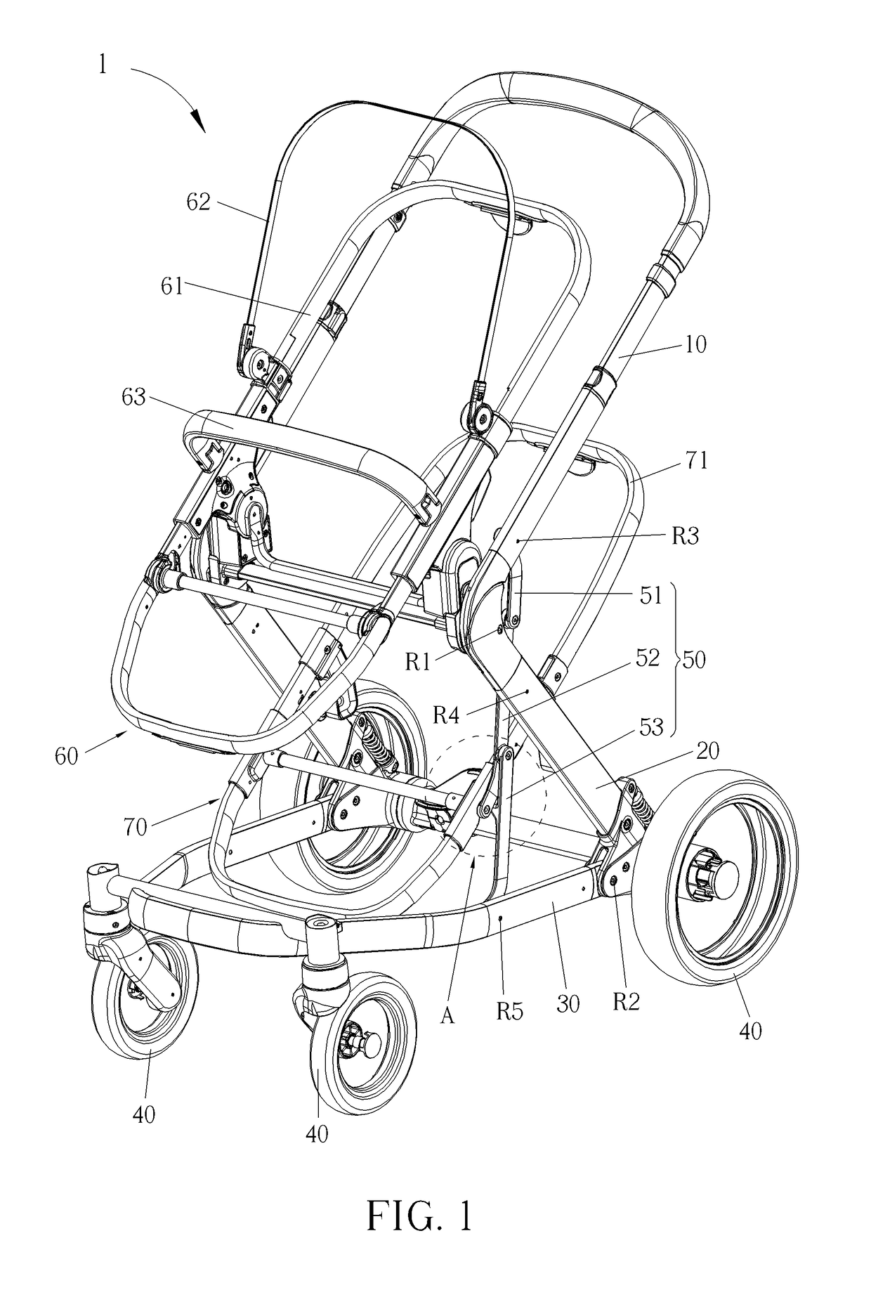
[0064]Please refer to FIG. 1. FIG. 1 is a schematic diagram of a stroller frame 1 according to the present invention. As shown in FIG. 1, the stroller frame 1 includes two handles 10, two rear feet 20, a bottom pipe 30, four wheels 40, at least one linking component 50, a first seat 60, and a carrier device. The two handles 10 are pivoted to the two rear feet 20 respectively. The two rear feet 20 are pivoted to the bottom pipe 30. Two of the four wheels 40 are disposed on a front side of the bottom pipe 30, and the other two of the four wheels 40 are disposed on a rear side of the bottom pipe 30. The linking component 50 is pivotally bendable. In this embodiment, the carrier device can be a second seat 70 detachably disposed between the two rear feet 20. However, the carrier device of present invention also can be a basket or any other supporting component in another embodiment. Furthermore, the number and the configuration of the linking component 50 are not limited to this embodim...
second embodiment
[0093]Please refer to FIG. 22. FIG. 22 is a diagram of the fixing block 8213 shown in FIG. 21 at another view according to the present invention. As shown in FIG. 22, a receiving slot 8213a is formed on the fixing block 8213. Two sliding slots 8213b are formed on a bottom wall of the receiving slot 8213a. Two connecting holes 8213c are formed on two side walls of the receiving slot 8213a. The two driving blocks 8212 are slidably disposed inside the two sliding slots 8213b respectively. An end of the releasing grip 8211 with the two protruding ribs 8211a is received in the receiving slot 8213a. The two protruding ribs 8211a engage with the two recesses 8212a respectively. The releasing grip 8211 is rotatably connected to the two connecting holes 8213c respectively. When the releasing grip 8211 is operated to rotate, the two driving blocks 8212 are driven to move toward each other, such that the two engaging components 822 are pulled to be released by the two second pulling components...
PUM
 Abstract
Description
Claims
Application Information
 - R&D
- Intellectual Property
- Life Sciences
- Materials
- Tech Scout
- Unparalleled Data Quality
- Higher Quality Content
- 60% Fewer Hallucinations
Browse by: Latest US Patents, China's latest patents, Technical Efficacy Thesaurus, Application Domain, Technology Topic, Popular Technical Reports.
© 2025 PatSnap. All rights reserved.Legal|Privacy policy|Modern Slavery Act Transparency Statement|Sitemap|About US| Contact US: help@patsnap.com


