
Radar sensor

a technology of radar sensor and lens edge, applied in the field of radar sensor, can solve the problems affecting the performance or characteristics of the radar antenna, and achieve the effects of improving the mechanical structure of the module-like encapsulated radar sensor, reducing the risk and improving the suppression effect of radial electromagnetic radiation

Active Publication Date: 2017-09-19
ROBERT BOSCH GMBH
View PDF31 Cites 3 Cited by
  • Summary
  • Abstract
  • Description
  • Claims
  • Application Information

AI Technical Summary

Benefits of technology

[0009]This makes it possible to omit the use of a shielding metal surface which may reflect radar radiation and other electromagnetic radiation. A directional characteristic of the radar antenna may be immune to influence due to the absorbing material. This may result in improved operation of the radar sensor. Furthermore, it may be simpler to adapt the geometry of the radar sensor, in particular of the radar lens, to an emission characteristic of the radar antenna. This makes it possible to improve the control of the emission characteristic of the radar sensor and achieve savings in development and production costs.
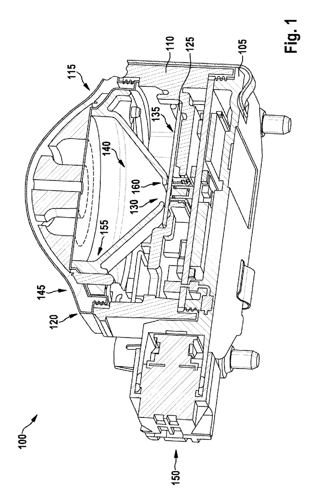
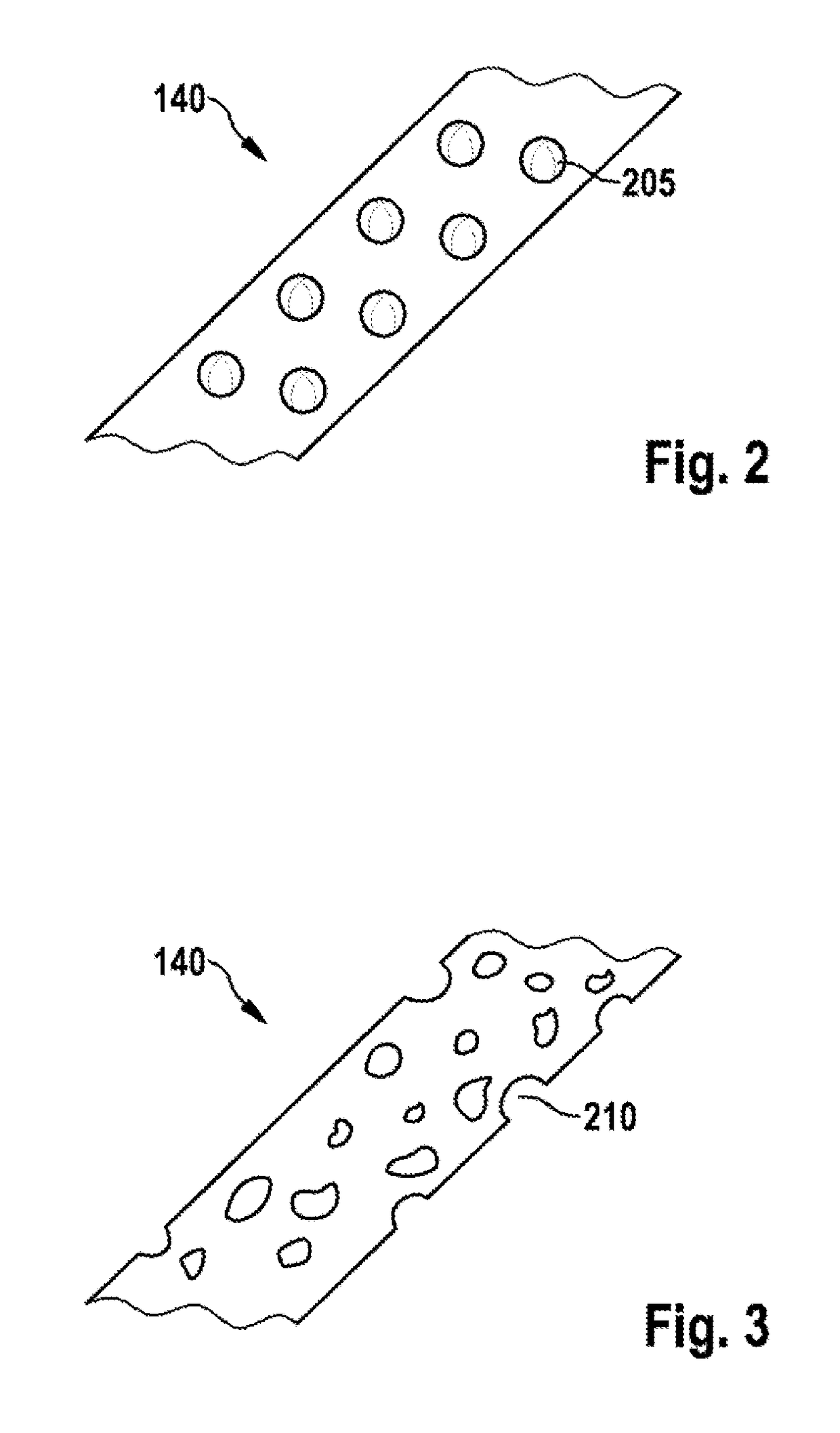
[0017]In one specific embodiment, the material of the funnel element is porous. Reflection and refraction of the radar radiation on pore boundaries may contribute to increasing the absorption capacity of the funnel element.

Problems solved by technology

This makes it possible to shield electromagnetic radiation and in particular the high-frequency radar radiation, so that the high-frequency circuit and the radar antenna do not mutually influence one another; however, this may also adversely affect the performance or characteristics of the radar antenna.

Method used


Image

  • Radar sensor
  • Radar sensor
  • Radar sensor

Examples


Embodiment Construction

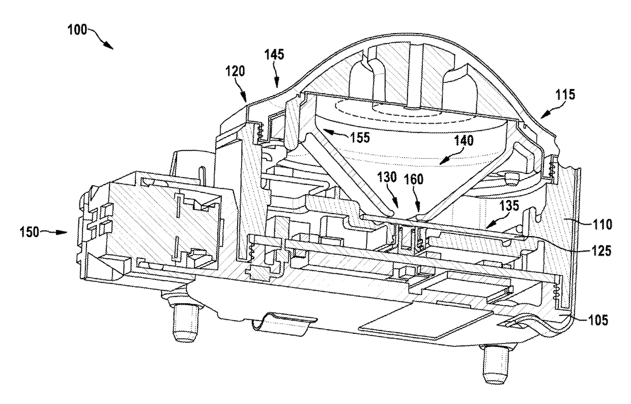
[0021]FIG. 1 shows a radar sensor 100. Radar sensor 100 is in particular designed for use in a motor vehicle. Radar sensor 100 is preferably a long-range radar sensor (LRR) for determining a distance and if necessary a speed of an object at a distance of up to several hundreds of meters. The radar radiation emitted by radar sensor 100 is preferably in the range of approximately 24 GHz or 77 GHz.

[0022]Radar sensor 100 includes a base plate 105 and a radar lens 115, which close a housing 110 at diametrically opposed ends. In other specific embodiments, the components of radar sensor 100 may also be protected from environmental influences in some other way than by housing 110 and base plate 105. Radar lens 115 has a radially outer lens edge 120, which may be attached to housing 110. Furthermore, the radar sensor includes a circuit substrate or a printed circuit board 125, on which a radar antenna 130 and a high-frequency circuit 135 are situated. Radar antenna 130 may be formed on prin...


PUM


Abstract

A radar sensor includes: a radar antenna, a radar lens and a funnel element between the radar antenna and the radar lens. The funnel element includes a material which absorbs the radar radiation emitted by the radar antenna.

Description

BACKGROUND OF THE INVENTION[0001]1. Field of the Invention[0002]The present invention relates to a radar sensor, e.g., a radar sensor for distance measurement in a motor vehicle.[0003]2. Description of the Related Art[0004]In a motor vehicle, a radar sensor may be used for determining a distance to a surrounding object. Based on the determined distance, different comfort and convenience functions of the motor vehicle may be controlled. For example, a speed of the motor vehicle may be automatically controlled to a predetermined value, a forward distance measurement with the aid of the radar sensor ensuring that the vehicle maintains a predetermined safety distance to a preceding motor vehicle. Other applications of a radar sensor include an emergency brake function when rapidly approaching an object, a distance warning device for making it easier for a driver of the motor vehicle to maintain a safety distance to a preceding vehicle, or a parking assistant for collision warning in clo...

Claims


Application Information

Patent Timeline
Patent Type & Authority Patents(United States)
IPC IPC(8): H01Q17/00H01Q1/32G01S13/93H01Q19/06G01S13/02G01S7/02G01S13/931
CPCH01Q17/008G01S7/02G01S13/02G01S13/931H01Q1/3233H01Q17/00H01Q19/06G01S2007/027G01S2013/9321G01S2013/9325G01S7/027
Inventor BINZER, THOMASHELLINGER, RAPHAELPONTES, JUAN
Owner ROBERT BOSCH GMBH
Learn More