Binding machine for agriculture

a technology for binding machines and agriculture, applied in agriculture, hand equipment, agricultural tools and machines, etc., can solve the problems of deteriorating binding accuracy, affecting the accuracy of binding, and requiring a lot of force on the lever, so as to achieve less force, less force, and smooth pulling out the steel needle

Active Publication Date: 2017-08-22
CHO NAM SUN
View PDF23 Cites 7 Cited by
  • Summary
  • Abstract
  • Description
  • Claims
  • Application Information

AI Technical Summary

Benefits of technology

[0005]The binding machine for agriculture according to the present invention has the following advantageous effects. The binding steel needle group is loaded into the steel needle supply part of the body of the binding machine, and the operation lever is pressed when it needs to start a binding work, and the steel needle extrusion plate is inputted into the input port of the steel needle exit, and the steel needle extrusion plate is inputted into the input port, and the steel needle which standbys in the steel needle exit is pushed out, and the pushed steel needle moves toward the steel needle bending and forming groove through the binding tape. Both ends of the steel needle are bent by a steel needle bending and forming part, and the binding tape is bound. A cutting knife cuts off the outer portions of the bound tape for thereby finishing a binding work.
[0006]The present invention has features in that when the steel needle extrusion plate pushes out a binding steel needle, the steel needle separation protrusion attached to a side surface of the binding steel needle extrusion plate separates out one steel needle attached to the steel needle group and moves it toward the steel needle exit, and the separated binding steel needle stands by in the standby groove, and the binding steel needle, which has been first separated and stands by, is extruded to the extrusion plate and comes out of the steel needle exit and comes to bind the tape. When the steel needle extrusion plate returns back, it separates from the steel needle group, and the binding steel needle, which stands by in the standby groove, receives a pressure from the spring and moves to the steel needle exit and stands by at the steel needle exit. The front end of the steel needle group comes into close contact with the side surface of the standby binding steel needle. For the sake of the next work, when the steel needle extrusion plate is inputted into the input port, the standby binding steel needle is pushed by the steel needle extrusion plate, and it moves to the steel needle exit. When the binding steel needle staying at the steel needle exit comes out of the exit and is bound to the binding tape, the steel needle separation protrusion formed at the side surface of the steel needle extrusion plate comes into contact with the bonding part of the steel needle group for thereby separating one by one the steel needles, and the separated steel needles are moved from the traveling path of the extrusion plate to the standby groove in the middle of the steel needle separation procedure. As the above mentioned procedures are repeatedly performed, the binding steel needle separation work and the extrusion forming work are separately performed, so it is possible to push out the steel needle more smoothly with less force as compared with when operating the operation lever and to bind the binding tape. Thanks to the above mentioned step-by-step procedures, less force is required when pushing out the steel needle extrusion plate along with decreased resistances, which results in smoothly pushing out the extrusion plate. For this, works becomes easier, and binding work can be accurately performed for thereby enhancing work efficiency. Any transformation of the extrusion plate can be prevented, and possible errors in machines can be prevented. The durability of machines can be enhanced. When binding the support string to the agricultural crop instead of the pole, the support strip 15 is forced to pass through the support strip guide groove 3e formed between the outer side of the steel needle exit and the binding steel needle bending and forming part 5b for thereby binding the binding steel needles, which makes the works easier.

Problems solved by technology

For this, the operation of the lever requires a lot of force when the worker starts operating the lever, as a result of which the worker may be easily tired and exhausted when working for a long time.
Since a certain resistance which occurs in the middle of the operation of the machine is great, the steel needle extrusion plate may be transformed, so it does not come into contact with the pressing position of the binding steel needle for thereby deteriorating the binding accuracy, which results in the errors in operation and bad workability.

Method used


Image

  • Binding machine for agriculture
  • Binding machine for agriculture
  • Binding machine for agriculture

Examples


Embodiment Construction

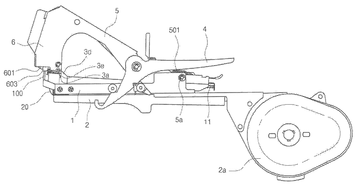
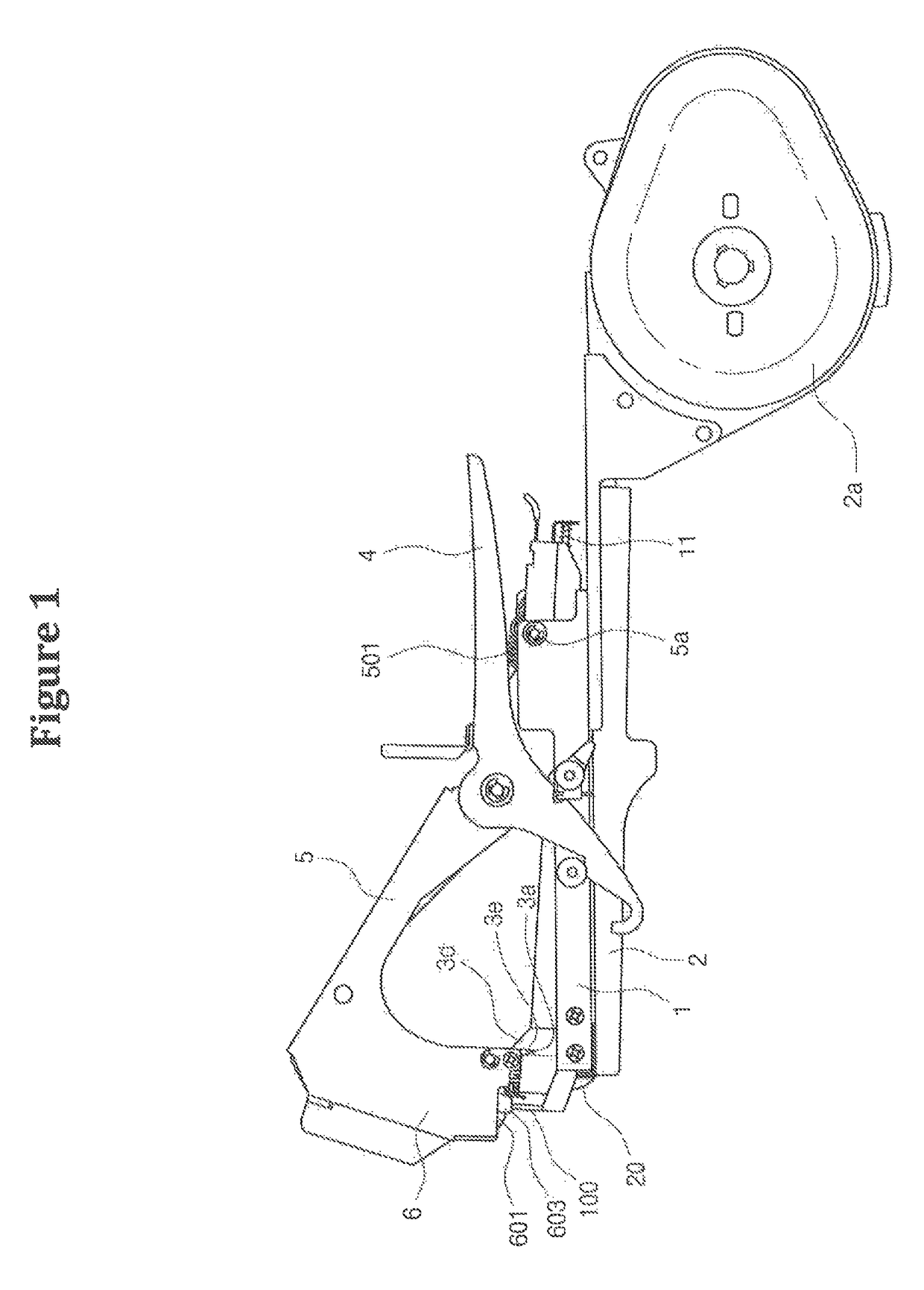
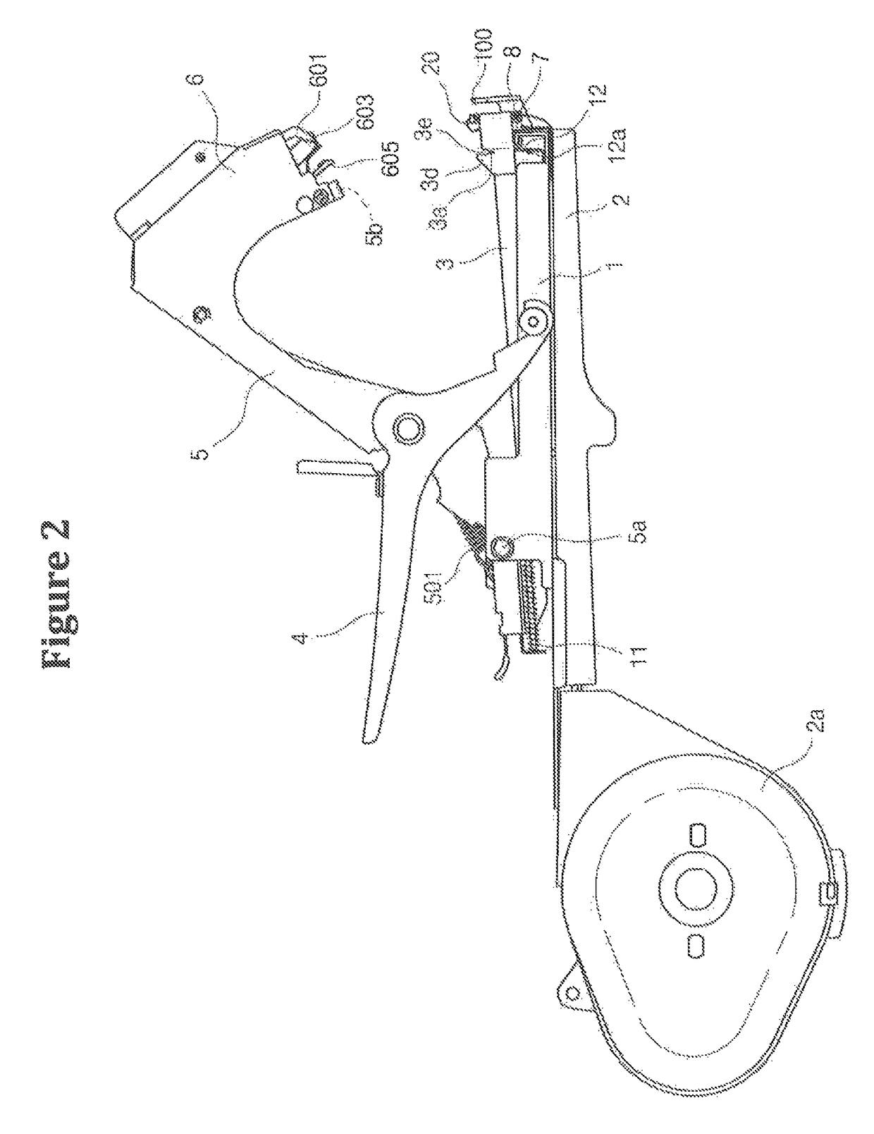
[0018]In a binding machine for agriculture in which a steel needle supply part 3 loading a steel needle group formed by bonding with an adhesive a plurality of steel needle 10a with their edges being close to one another is provided in the interior of a binding unit body 1, and at its front end is formed a steel needle exit 3a, and a spring 11 is disposed so as to push the steel needle group to the steel needle exit from the opposite side, and a steel needle cover 30 is formed at an inner side of the steel needle supply unit 3, and an input port 30a is formed at a front end for allowing a steel needle extrusion plate to come in and go out, and a steel needle extrusion plate 12 is attached vertical to the binding unit body, so one binding steel needle can be pushed out through the input port of the steel needle extrusion plate, and a tape cutting compartment 3c and a tape discharge compartment 8 are formed at the front portion of the binding unit body, and the tape storage compartmen...


PUM

PropertyMeasurementUnit
widthaaaaaaaaaa
forceaaaaaaaaaa
pressureaaaaaaaaaa

Abstract

Disclosed is a binding machine for agriculture which is used when binding, using a binding tape, a crop to a pole which is previously installed near the crop so as to keep in places the stems or branches of various crops. A steel needle standby groove is formed at an inner side of the steel 5 needle exit of the steel needle supply part loaded with binding steel needles, and when steel needles are extruded, the steel needle is separated from the steel needle group and stands by in the steel needle standby groove, and in the steel needle extrusion plate, a steel needle separation protrusion is formed at a side surface 10 in the direction of the steel needle standby groove, and then the binding steel needle is extruded.

Description

TECHNICAL FIELD[0001]The present invention relates to a binding machine for agriculture which is used when binding, using a binding tape, a crop to a pole which is previously installed near the crop so as to keep in place the stems or branches of various crops, and in particular to a binding machine for agriculture which makes it possible to mitigate a worker's work load and to obtain a precise binding work which is generally done using a steel needle along with an enhanced reliability in work by preventing the possible errors in machine, the advantages of which are obtained in such a way that when tying a binding tape by extruding a binding steel core of a binding machine through an exit, a work for extruding a binding steel needle can be done easily with less force.BACKGROUND ART[0002]The binding machine for agriculture has features in that a number of binding steel needles are adhered with their sides being arranged to be neighbored to each other and are loaded into a steel needl...

Claims


Application Information

Patent Timeline
Patent Type & Authority Patents(United States)
IPC IPC(8): A01F1/04A01G17/08
CPCA01G17/085A01G17/08
Inventor CHO, NAM SUN
Owner CHO NAM SUN
Why Eureka
Try Eureka